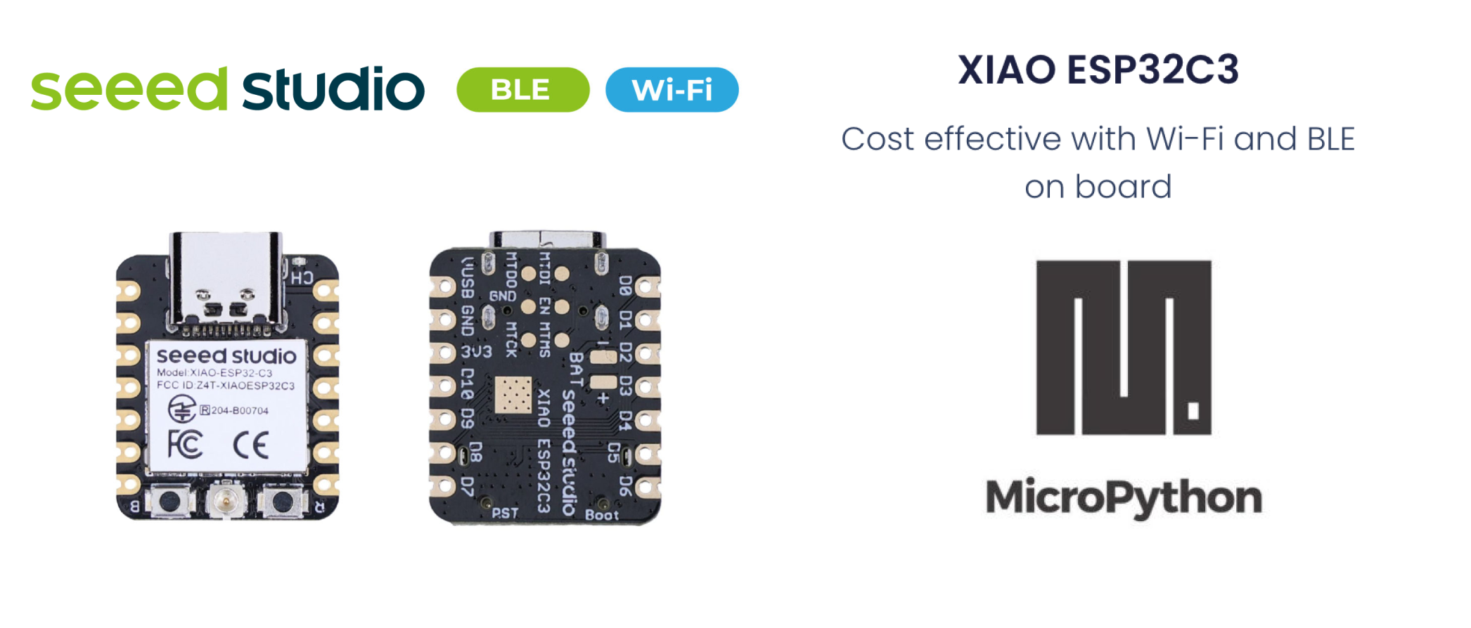
Seeed Studio XIAO ESP32C3 with MicroPython
MicroPython is a Python interprer with a partial native code compilation feature. It provides a subset of Python 3.5 features, implemented for embedded processors and constrained systems. It is different from CPython and you can read more about the differences here.
Installing MicroPython
Install Esptool
If you haven't already installed esptool.py, you can do so using pip on your pc:
pip install esptool
Download the XIAO ESP32C3 MicroPython firmware
You need to download the firmware binary file from micropython.org After downloading correct bin file, navigate to the folder, and open a cmd terminal there. As of the final draft, the latest version of bin file is:
ESP32_GENERIC_C3-20230602-v1.23.0.bin
Connect the XIAO ESP32C3 on your PC
You need to press and hold down BOOT button on your XIAO ESP32C3 board to enter the 'bootloader' mode while pluging in to the type C USB cable to your pc.
Check port
Find out all serial devices on your pc.
- Linux
On Linux, you can use the dmesg command to view connected devices:
dmesg | grep tty
Alternatively, you can list serial devices using ls:
ls /dev/ttyS* /dev/ttyUSB*
- Window
On Windows, you can check serial ports through Device Manager. Look for the “Ports (COM & LPT)” section to see the available serial ports. You can also use the mode command in Command Prompt to list serial ports:
mode
- macOS
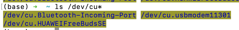
On macOS, you can list available serial ports using the ls command:
ls /dev/cu*
This will show all serial port devices.
If the port is busy, you can use the following command to find an dkill and processes using the port(On macOS): Identify processes using the port:
lsof | grep port
This command lists open files and searches for any process using the specified port. Find the process ID(PID) from the output and kill the procee:
kill -9 <PID>
Replace PID with the actual process ID found.
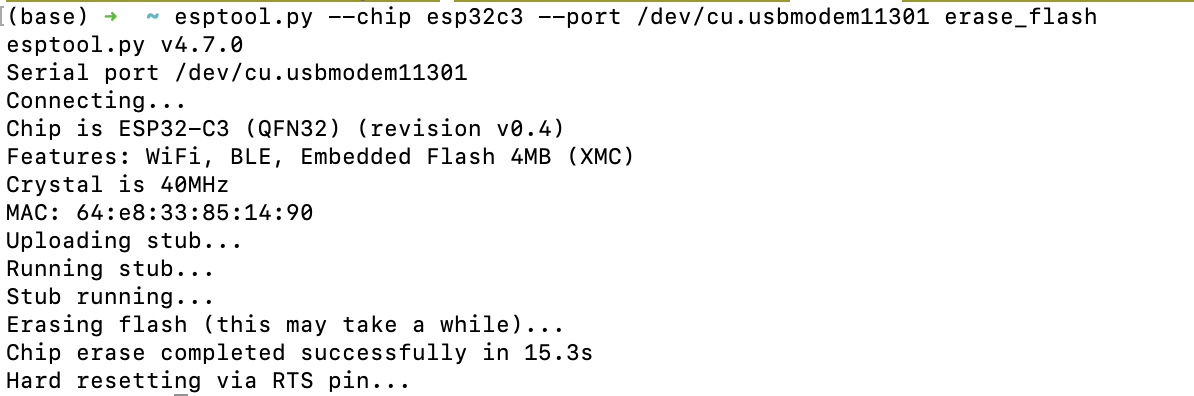
Erase flash
esptool.py --chip esp32c3 --port /dev/cu.usbmodem11301 erase_flash
Replace '/dev/cu.usbmodem11301' with the correct port name from your system(e.g. COM3 on Windows, /dev/ttyUSB0 on linux).
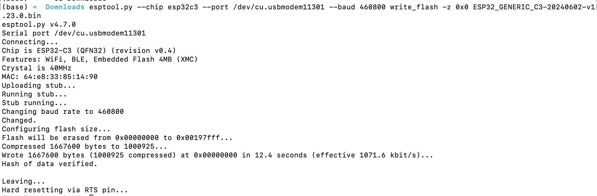
Write flash
Flash the firmware onto XIAO ESP32C3:
esptool.py --chip esp32c3 --port /dev/cu.usbmodem11301 --baud 460800 write_flash -z 0x0 ESP32_GENERIC_C3-20240602-v1.23.0.bin
Again, replace '/dev/cu.usbmodem11301' with the correct port name, and 'ESP32_GENERIC_C3-20240602-v1.23.0.bin' with the path to your blank firmware file.
Then can start to compile script using your prefer tool to ESP32!
Recommended Editors for MicroPython
Some of popular tools are listed below.
1. Thonny
Install and open thonny, then configure Thonny following the instruction:
pip install thonny
#open thonny after installation
thonny
Go to Run-->Configure Interpreter, and ensure that the Interpreter tab in the Thonny options looks as shown below, select "CircuitPython (generic)" and port:
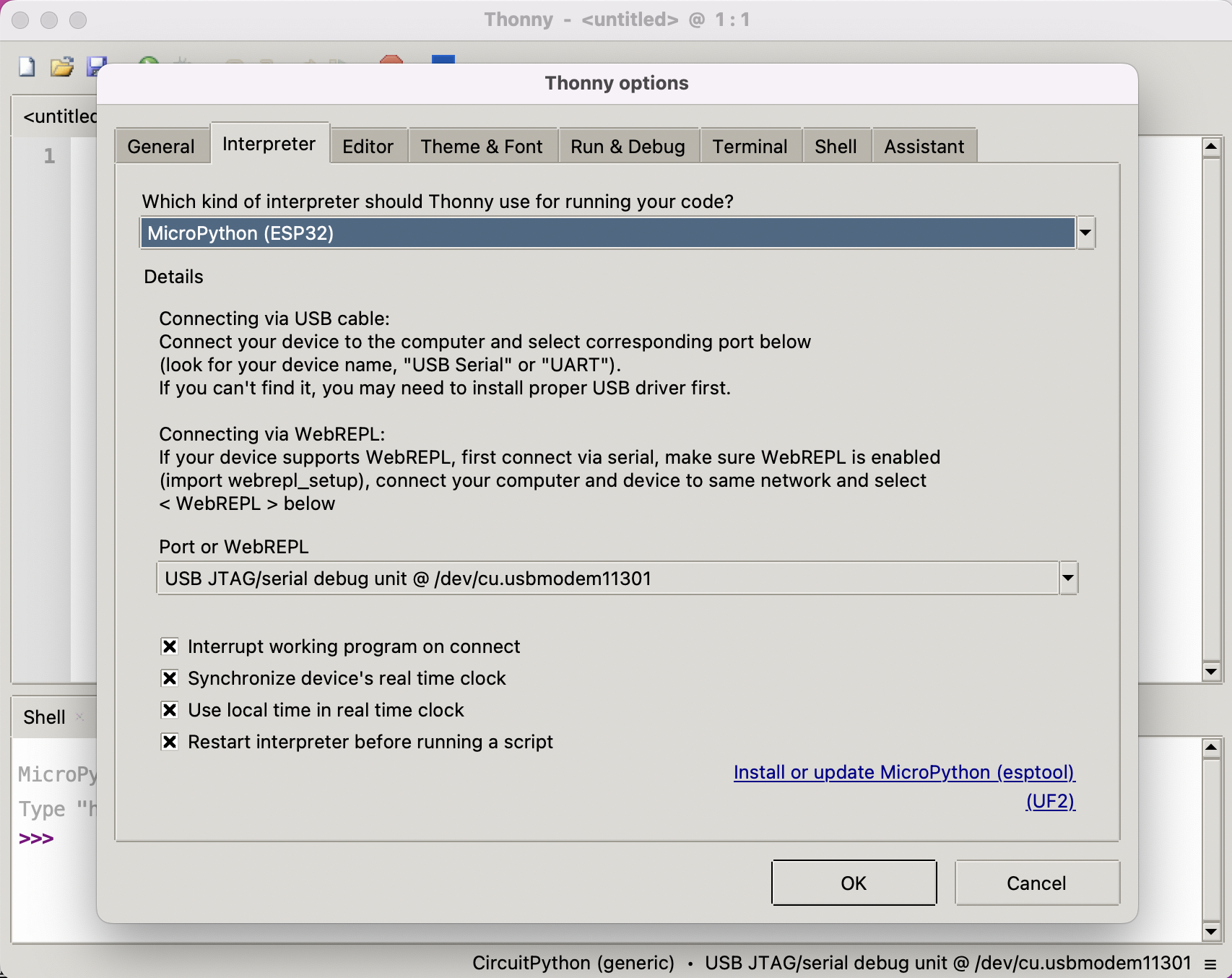
Click "OK" on the dialog and you should be presented with the Micropython shell at the bottom of the thonny window as shown in the figure below. Enter scripy line by line to the Shell to get the flash and sram size:
import gc
gc.mem_free()

import esp
esp.flash_size()
Congratulations on successfully setting up MicroPython on your XIAO ESP32C3 with Thonny!
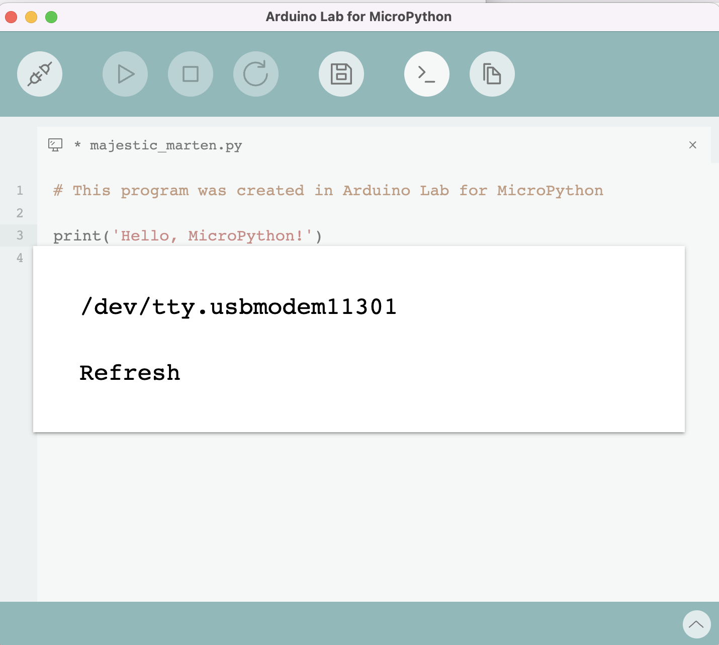
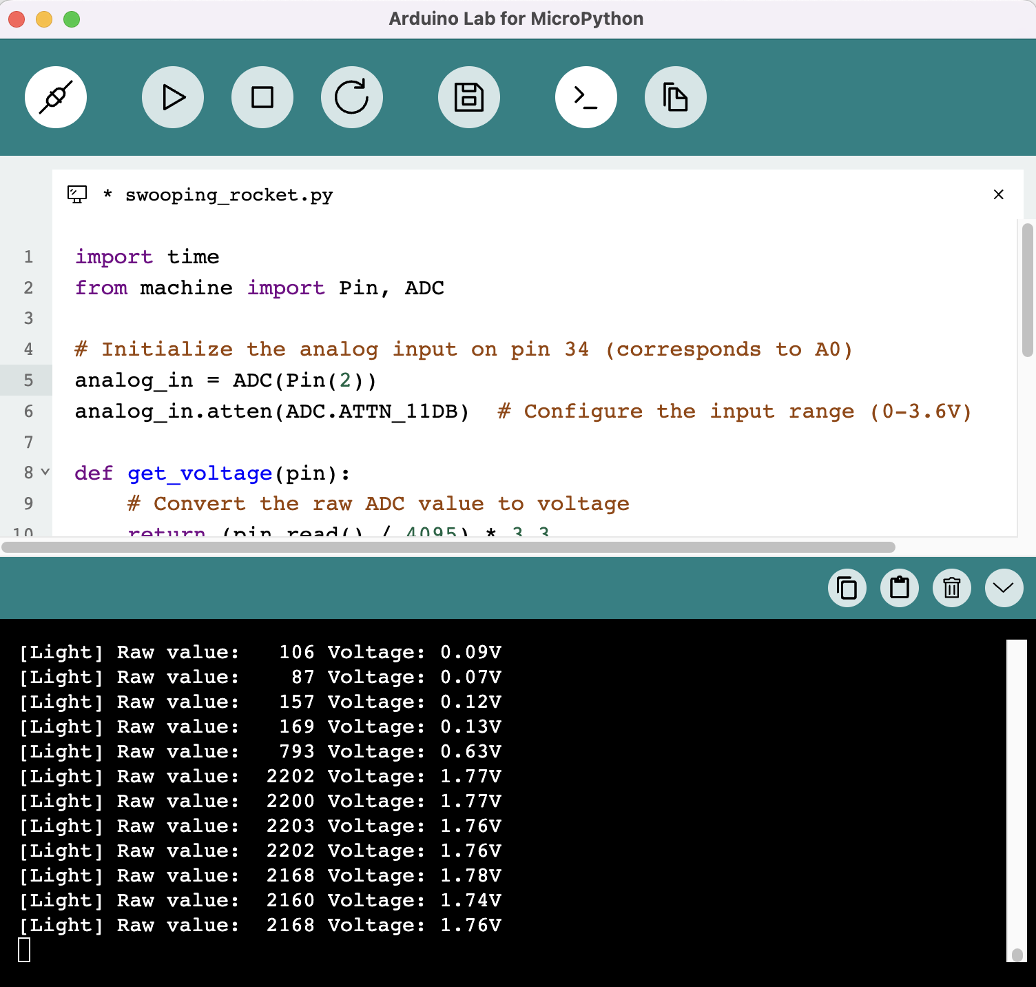
2. Arduino Lab for MicroPython
Download Arduino lab for MicroPython and connect the device to your pc.
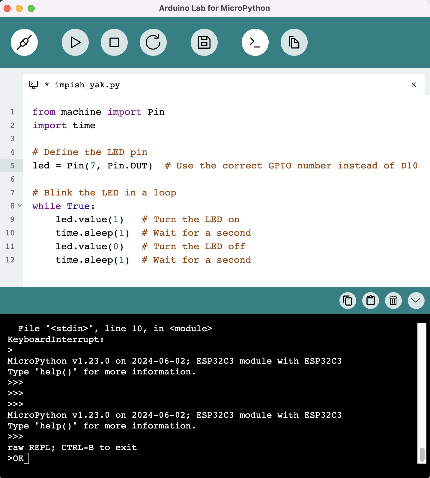
Code like this:
from machine import Pin
import time

# Define the LED pin
led = Pin(7, Pin.OUT)  # Use the correct GPIO number instead of D10

# Blink the LED in a loop
while True:
    led.value(1)   # Turn the LED on
    time.sleep(1)  # Wait for a second
    led.value(0)   # Turn the LED off
    time.sleep(1)  # Wait for a second
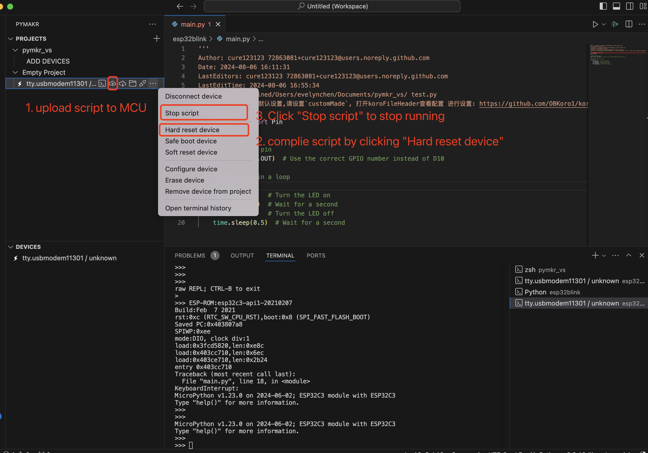
3. Pymakr on Visual Studio Code
-
Install Pymakr Follow the installation instructions to install Pymakr.
-
Connect Your XIAO ESP32C3 to your computer.
-
Create a New Project Open VS Code and create a new project for your microcontroller.
-
Add a New Python File Create a new Python file within your project.
-
Upload Script to MCU and Compile the Script
4. uPtCraft IDE
Pinout/Port Information
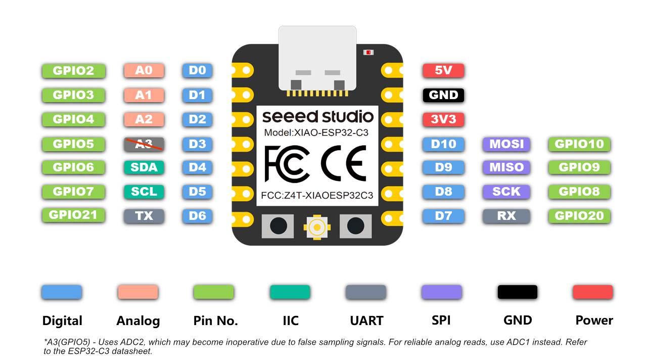
- More information please refer to hardware overview
- Seeed Studio XIAO ESP32C3 Schematic
Getting Started with MicroPython on the XIAO ESP32C3
Here is a quick reference for ESP32 operation by micropython. For more knowledge about micropython libraries.
General board control
The MicroPython REPL(Read-Eval-Print-Loop) is on UART0 (GPIO1=TX, GPIO3=RX) at baudrate 115200. Tab-completion is useful to find out what methods an object has. Paste mode (ctrl-E) is useful to paste a large slab of Python code into the REPL. Can use the dir() function in MicroPython(similar in Python) to list the attributes and methods of an object. For example, enter dir(machine) to shell:
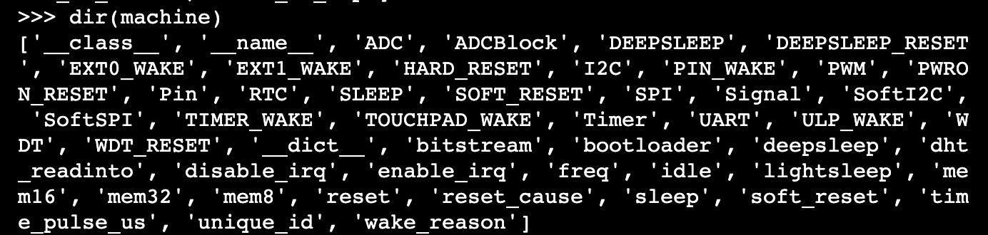
The machine module:
import machine
machine.freq()          # get the current frequency of the CPU, for esp32c3 is 160000000
machine.freq(160000000) # set the CPU frequency to 160 MHz
The esp module:
import esp

esp.osdebug(None)       # turn off vendor O/S debugging messages
esp.osdebug(0)          # redirect vendor O/S debugging messages to UART(0)

# low level methods to interact with flash storage
esp.flash_size()
esp.flash_user_start()
esp.flash_erase(sector_no)
esp.flash_write(byte_offset, buffer)
esp.flash_read(byte_offset, buffer)
The esp32 module: ESP32C3, ESP32S2, and ESP32S3 have an internal temperature sensor available and returns the temperature in Celsius:
import esp32
esp32.mcu_temperature() # read the internal temperature of the MCU, in Celsius
Network-WLAN
The Network module: More information refer to here.
import network

wlan = network.WLAN(network.STA_IF) # create station interface
wlan.active(True)       # activate the interface
wlan.scan()             # scan for access points
wlan.isconnected()      # check if the station is connected to an AP
wlan.connect('ssid', 'key') # connect to an AP
wlan.config('mac')      # get the interface's MAC address
wlan.ifconfig()  # get the interface's IPv4 addresses

ap = network.WLAN(network.AP_IF) # create access-point interface
ap.config(ssid='ESP-AP') # set the SSID of the access point
ap.config(max_clients=10) # set how many clients can connect to the network
ap.active(True)         # activate the interface
A useful function for connecting to your local WiFi network is:
def do_connect():
    import network
    wlan = network.WLAN(network.STA_IF)
    wlan.active(True)
    if not wlan.isconnected():
        print('connecting to network...')
        wlan.connect('ssid', 'key') #replace the ssid and key
        while not wlan.isconnected():
            pass
    print('network config:', wlan.ifconfig())
Delay and timing
The time module:
import time

time.sleep(1)           # sleep for 1 second
time.sleep_ms(500)      # sleep for 500 milliseconds
time.sleep_us(10)       # sleep for 10 microseconds
start = time.ticks_ms() # get millisecond counter
delta = time.ticks_diff(time.ticks_ms(), start) # compute time difference
Timers
The ESP32 port has four hardware timers. Use the class with a timer ID from 0 to 3 (inclusive):
from machine import Timer

tim0 = Timer(0)
tim0.init(period=5000, mode=Timer.ONE_SHOT, callback=lambda t:print(0))

tim1 = Timer(1)
tim1.init(period=2000, mode=Timer.PERIODIC, callback=lambda t:print(1))
The period is in milliseconds. Virtual timers are not currently supported on this port.
Pins and GPIO
The machine.Pin class:
from machine import Pin

p2 = Pin(2, Pin.OUT)    # create output pin on GPIO2
p2.on()                 # set pin to "on" (high) level
p2.off()                # set pin to "off" (low) level
p2.value(1)             # set pin to on/high

p3 = Pin(3, Pin.IN)     # create input pin on GPIO3
print(p3.value())       # get value, 0 or 1

p4 = Pin(4, Pin.IN, Pin.PULL_UP) # enable internal pull-up resistor
p5 = Pin(5, Pin.OUT, value=1) # set pin high on creation
p6 = Pin(6, Pin.OUT, drive=Pin.DRIVE_3) # set maximum drive strength
Available Pins are from the following ranges (inclusive): 2,3,4,5,6,7,8,9,10,20,21. These correspond to the actual GPIO pin numbers of ESP32C3 chip.
UART(serial bus)
The machine.UART class:
from machine import UART

uart1 = UART(1, baudrate=9600, tx=21, rx=20)
uart1.write('hello')  # write 5 bytes
uart1.read(5)         # read up to 5 bytes
The ESP32C3 have one hardware UART. the pins listed below:
| UART | Pin |
|---|---|
| TX | 21 |
| RX | 20 |
PWM(pulse width modulation)
PWM can be enabled on all output-enabled pins. The base frequency can range from 1Hz to 40MHz but there is a tradeoff; as the base frequency increases the duty resolution decreases. The machine.PWM class:
from machine import Pin, PWM

pwm2 = PWM(Pin(2), freq=5000, duty_u16=32768) # create PWM object from a pin
freq = pwm2.freq()         # get current frequency
pwm2.freq(1000)            # set PWM frequency from 1Hz to 40MHz

duty = pwm2.duty()         # get current duty cycle, range 0-1023 (default 512, 50%)
pwm2.duty(256)             # set duty cycle from 0 to 1023 as a ratio duty/1023, (now 25%)

duty_u16 = pwm2.duty_u16() # get current duty cycle, range 0-65535
pwm2.duty_u16(2**16*3//4)  # set duty cycle from 0 to 65535 as a ratio duty_u16/65535, (now 75%)

duty_ns = pwm2.duty_ns()   # get current pulse width in ns
pwm2.duty_ns(250_000)      # set pulse width in nanoseconds from 0 to 1_000_000_000/freq, (now 25%)

pwm2.deinit()              # turn off PWM on the pin

pwm3 = PWM(Pin(3), freq=20000, duty=512)  # create and configure in one go
print(pwm3)                               # view PWM settings
ESP chips have different hardware peripherals:
| Hardware Specification | ESP32C3 | ESP32 |
|---|---|---|
| Number of groups (speed modes) | 1 | 2 |
| Number of timers per group | 4 | 4 |
| Number of channels per group | 6 | 8 |
| Different PWM frequencies (groups * timers) | 4 | 8 |
| Total PWM channels (Pins, duties) (groups * channels) | 6 | 16 |
ADC(analog to digital conversion)
On XIAO ESP32C3, ADC functionality is available on pins 2,3,4.
A3(GP105) - Uses ADC2, which may become inoperative due to false sampling signals. For analog reads, use ADC1(A0/A1/A2) instead. Refer to the XIAO ESP32C3 datasheet.
The machine.ADC class:
from machine import ADC

adc = ADC(pin)        # create an ADC object acting on a pin
val = adc.read_u16()  # read a raw analog value in the range 0-65535
val = adc.read_uv()   # read an analog value in microvolts
SPI
Software SPI bus
Software SPI (using bit-banging) works on all pins, and is accessed via the machine.SoftSPI class:
from machine import Pin, SoftSPI

# construct a SoftSPI bus on the given pins
# polarity is the idle state of SCK
# phase=0 means sample on the first edge of SCK, phase=1 means the second
spi = SoftSPI(baudrate=100000, polarity=1, phase=0, sck=Pin(2), mosi=Pin(4), miso=Pin(6))

spi.init(baudrate=200000) # set the baudrate

spi.read(10)            # read 10 bytes on MISO
spi.read(10, 0xff)      # read 10 bytes while outputting 0xff on MOSI

buf = bytearray(50)     # create a buffer
spi.readinto(buf)       # read into the given buffer (reads 50 bytes in this case)
spi.readinto(buf, 0xff) # read into the given buffer and output 0xff on MOSI

spi.write(b'12345')     # write 5 bytes on MOSI

buf = bytearray(4)      # create a buffer
spi.write_readinto(b'1234', buf) # write to MOSI and read from MISO into the buffer
spi.write_readinto(buf, buf) # write buf to MOSI and read MISO back into buf
Hardware SPI bus
Hardware SPI is accessed via the machine.SPI class and has the same methods as software SPI above:
from machine import Pin, SPI

hspi = SPI(1, 10000000)
hspi = SPI(1, 10000000, sck=Pin(8), mosi=Pin(10), miso=Pin(9))
| SPI | Pin |
|---|---|
| SCK | D8 |
| MOSI | D10 |
| MISO | D9 |
I2C
Software I2C bus
Software I2C (using bit-banging) works on all output-capable pins, and is accessed via the machine.SoftI2C class:
from machine import Pin, SoftI2C

i2c = SoftI2C(scl=Pin(7), sda=Pin(6), freq=100000)

i2c.scan()              # scan for devices

i2c.readfrom(0x3a, 4)   # read 4 bytes from device with address 0x3a
i2c.writeto(0x3a, '12') # write '12' to device with address 0x3a

buf = bytearray(10)     # create a buffer with 10 bytes
i2c.writeto(0x3a, buf)  # write the given buffer to the peripheral
Hardware I2C bus
The driver is accessed via the machine.I2C class and has the same methods as software I2C above:
from machine import Pin, I2C
i2c = I2C(0, scl=Pin(7), sda=Pin(6), freq=400000)
| I2C | GPIO | Pin |
|---|---|---|
| SCL | GPIO7 | D5 |
| SDA | GPIO6 | D4 |
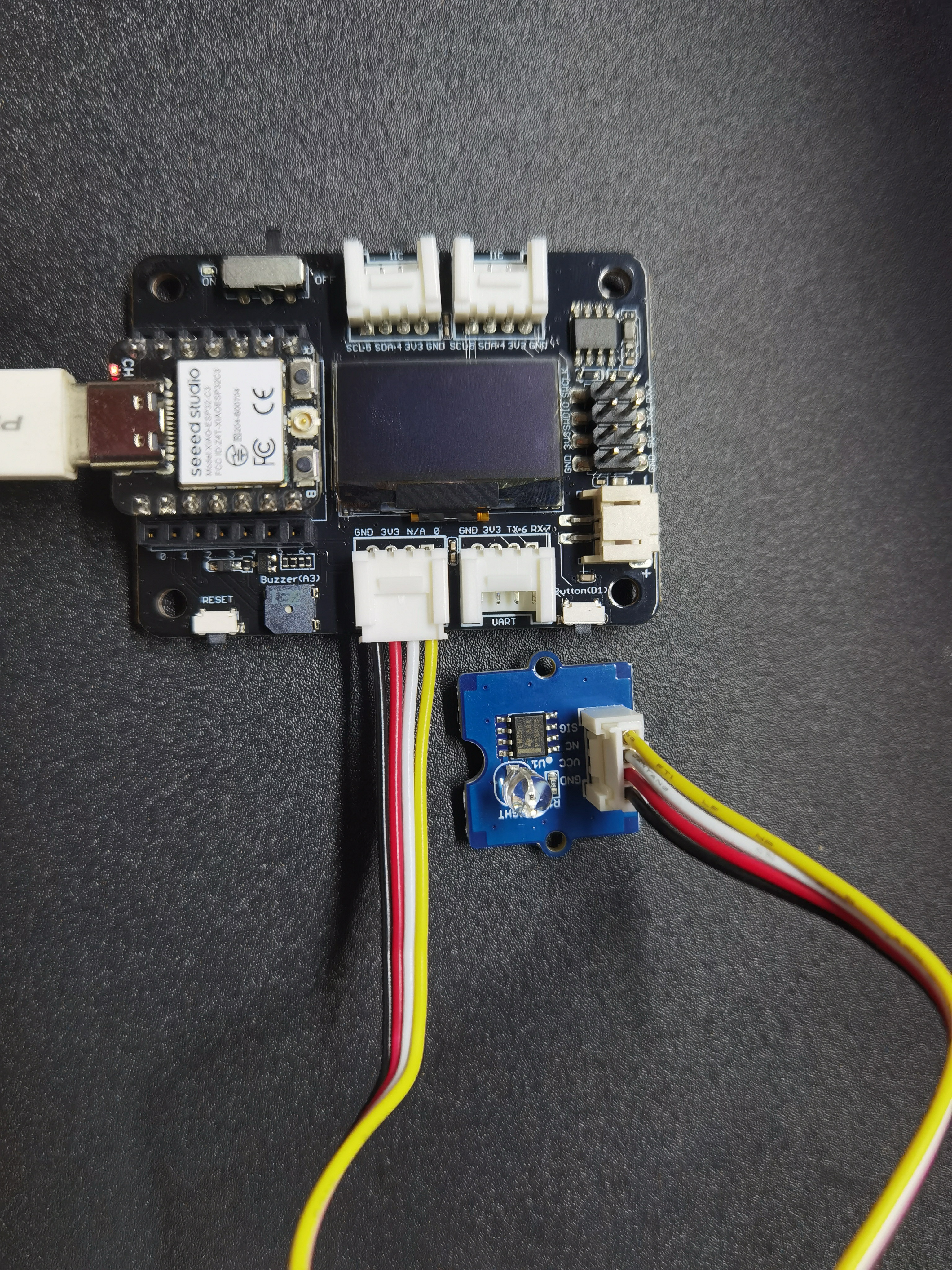
Expension Board Base for XIAO
Prerequisites:
| XIAO ESP32C3 with soldered header | Expension Board Base for XIAO | Grove Light sensor |
|---|---|---|
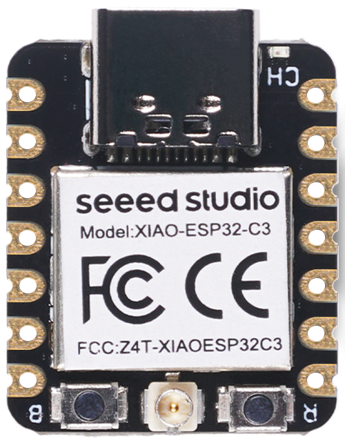 |  |  |
Read the light sensor data
import time
from machine import Pin, ADC

# Initialize the analog input on pin 2 (corresponds to A0)
analog_in = ADC(Pin(2))
analog_in.atten(ADC.ATTN_11DB)  # Configure the input range (0-3.6V)

def get_voltage(pin):
    # Convert the raw ADC value to voltage
    return (pin.read() / 4095) * 3.3

while True:
    # Read the raw analog value
    raw_value = analog_in.read()
    # Convert the raw value to voltage
    voltage = get_voltage(analog_in)

    # Print the raw value and voltage to the serial console
    print("[Light] Raw value: {:5d} Voltage: {:.2f}V".format(raw_value, voltage))

    # Delay for a short period of time before reading again
    time.sleep(1)
Light up OLED screen
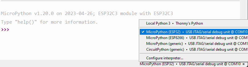
Plug in your XIAO ESP32C3, open Thonny and click right bottom to configure interpreter Select interpreter- Micropython (ESP32) and Port >>> Click OK
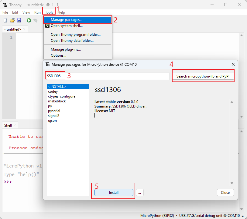
If everything goes well, you will see the output in the shell Install required libraries Click "Tools" >>> Click "Management Packages" >>> Enter Library's name >>> Click "Search micropython-lib and PyPl"
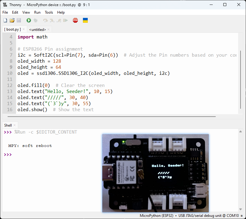
Run the scrip and Flash it to the board. After you finish coding, click the green button to run the script.
import time
from machine import Pin, SoftI2C
import ssd1306
import math

# Pin assignment
i2c = SoftI2C(scl=Pin(7), sda=Pin(6))  # Adjust the Pin numbers based on your connections
oled_width = 128
oled_height = 64
oled = ssd1306.SSD1306_I2C(oled_width, oled_height, i2c)

oled.fill(0)  # Clear the screen
oled.text("Hello, Seeder!", 10, 15)
oled.text("/////", 30, 40)
oled.text("(`3`)y", 30, 55)
oled.show()  # Show the text
Thank you for reading this article! Feel free to share your thoughts in the comments.
Resources
- The firmware binary file for XIAO ESP32C3 with MicroPython
Tech Support & Product Discussion
Thank you for choosing our products! We are here to provide you with different support to ensure that your experience with our products is as smooth as possible. We offer several communication channels to cater to different preferences and needs.