Grove Beginner Kit for Arduino Projects
Project 1: Intrusion Alarm
Overview
This wiki introduces how to make a intrusion alarm.
Feature
- The PIR motion sensor can detect people if in the area, then alarm triggered.
Component required
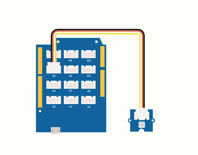
Hardware Connection
Please follow the same color line to connect each sensor on the board, put the PIR motion sensor grove cable to the D2.
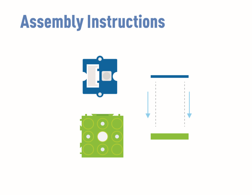
Assembly instructions
The buzzer (D5) and LED (D4) are embedded in the board.
Arduino Instructions
Step 1. Download the Aruidno IDE
Step 2. Follow the connection picture connect all the sensor on the board.
Step 3. Place the Mini PIR motion sensor in the location of the detection.
Step 4. Copy the code stick on the Aruino IDE then upload it.
Code
#define PIR_MOTION_SENSOR 2//Use pin 2 to receive the signal from the module

int BuzzerPin = 5;     // set D5 as buzzer
int LED_RAD = 4;       // set D4 as LED

void setup() {
  Serial.begin(9600);
  pinMode(PIR_MOTION_SENSOR, INPUT);
  pinMode(BuzzerPin, OUTPUT);
  pinMode(LED_RAD, OUTPUT);
}

void loop() {

  if (digitalRead(PIR_MOTION_SENSOR)) {
    analogWrite(BuzzerPin, 100);
    digitalWrite(LED_RAD, HIGH);
    delay(3000);
    analogWrite(BuzzerPin, 0);
    digitalWrite(LED_RAD, LOW);
    delay(4000);
  }

}
project 2: Oscillating fan
Overview
This wiki introduce how to make a Mini fan to plase on your room keep cool.
Feature
- Automatic swing fan
Component required
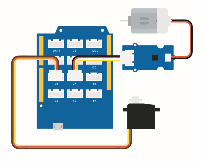
Hardware Connection
Please connect the fan grove cable to D7, Servo grove cable to D3.
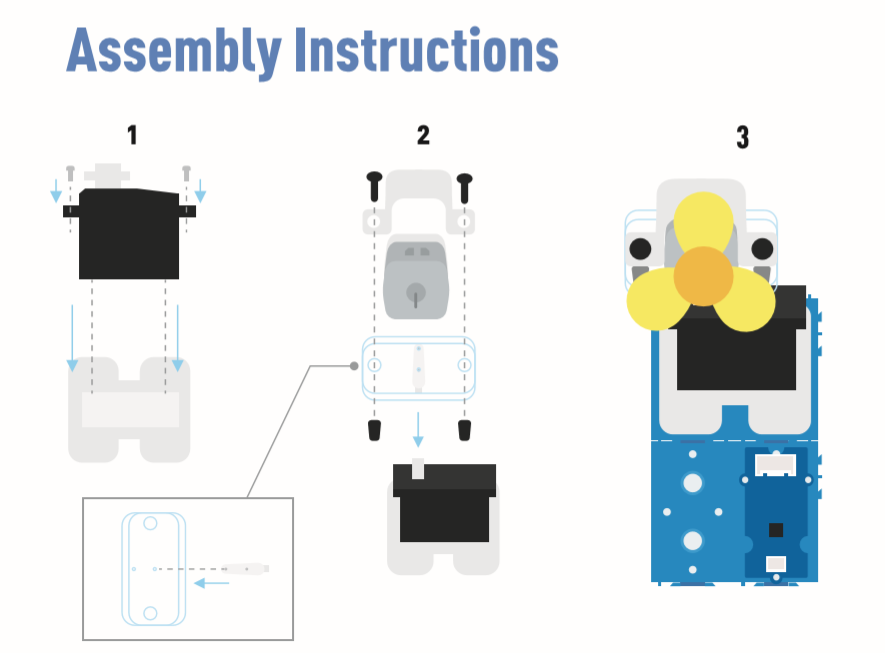
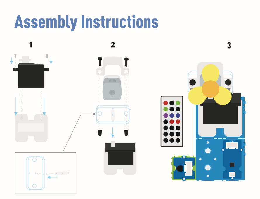
Assembly instruction
Arduino Instructions
Step 1. Download the Aruidno IDE
Step 2. Copy the Code and stick on the Arduino IDE
Step 3. Select the current port: Tools -> Port -> COM (number)
Step 4. Upload the code
Please set the fan in the safety position.
Code
#include <Servo.h>

Servo myservo;  // create servo object to control a servo

int pos = 0;    // variable to store the servo position
int fanPin = 7;  // set D6 as control switch
int fanState = LOW;

void setup() {
    Serial.begin(9600);
    myservo.attach(3);  // attaches the servo on pin 2 to the servo object
    pinMode(fanPin, OUTPUT);
}

void loop() {

 fanState = HIGH;
 digitalWrite(fanPin, fanState);

   for (pos = 0; pos <= 100; pos += 1) { // goes from 0 degrees to 100 degrees
    // in steps of 1 degree
    myservo.write(pos);              // tell servo to go to position in variable 'pos'
    delay(40);                       // waits 15ms for the servo to reach the position
  }
  for (pos = 100; pos >= 0; pos -= 1) { // goes from 100 degrees to 0 degrees
    myservo.write(pos);              // tell servo to go to position in variable 'pos'
    delay(40);                       // waits 15ms for the servo to reach the position
  }
}
Project 3: Remote Control Oscillating Fan
Overview
This wiki introduces how to make a remote control oscillating fan.
Feature
-
The fan power controlled by the controller.
-
The fan swing way is able to use remote control.
Component required
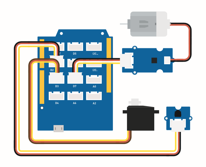
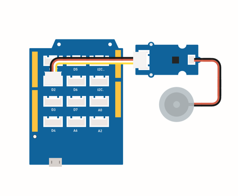
Hardware Connection
Please follow the same color line to connect each sensor on the board. Please connect the fan grove cable to D7, servo grove cable to D3, IR grove cable to D2.
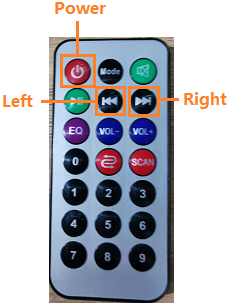
This is controller botton function.
Assembly instruction
Arduino Instructions
Step 1. Follow the connection picture connect all the sensor on the board.
Step 2. Download the Aruidno IDE
Step 3. Navigate to Sketch -> Include Library -> Manage Libraries, search IRremote then install it.
Step 4. Copy the code stick on the Aruino IDE then upload it.
Step 5. Place the Fan in the safety position, try to press the button make sure it can work safely.
Refer How to install library to install library for Arduino.
Code
#include <IRremote.h>
#include <Servo.h>

Servo myservo;  // create servo object to control a servo
int RECV_PIN = 2; // set pin 2 as IR control

IRrecv irrecv(RECV_PIN);

decode_results results;

int pos = 90;    // variable to store the servo position
int fanPin = 7;  // set D6 as control switch
int fanState = LOW;
int IO = 0;

void setup()
{
  Serial.begin(9600);
  Serial.println("Enabling IRin");  // remind enabling IR
  irrecv.enableIRIn(); // Start the receiver
  Serial.println("Enabled IRin");
  myservo.attach(3);  // attaches the servo on pin 2 to the servo object
  pinMode(fanPin, OUTPUT);

}

//  power_encode 2155829415     left  2155870215  right  2155821255

void loop() {
  if (irrecv.decode(&results)) { //checking IR signal
    if (results.value == 2155829415) {    // Power off/on
      IO++;
      if (IO % 2 == 0) {
        fanState = HIGH;
        digitalWrite(fanPin, fanState);
        delay(100);
      }
      else {
        fanState = LOW;
        digitalWrite(fanPin, fanState);
        delay(100);
      }
    }

    if (results.value == 2155821255 ) {    // fan swing to left
      for (pos; pos <= 89; pos += 1) { // goes from 0 degrees to 90 degrees
        // in steps of 1 degree
        myservo.write(pos);              // tell servo to go to position in variable 'pos'

        delay(40);                       // waits 15ms for the servo to reach the position
        if (irrecv.decode(&results)) {
          irrecv.resume();
          if (results.value == 2155870215)
            break;
        }
      }
    }

    if (results.value == 2155870215 ) {    // fan swing to right
      for (pos; pos >= 1; pos -= 1) { // goes from 90 degrees to 0 degrees
        myservo.write(pos);              // tell servo to go to position in variable 'pos'
        delay(40);                       // waits 15ms for the servo to reach the position

        if (irrecv.decode(&results)) {
          irrecv.resume();
          if (results.value == 2155821255)
            break;
        }
      }
    }
    Serial.println(pos);
    Serial.println(results.value, HEX);
    Serial.println(results.value);
    irrecv.resume();                    //recive next intrustion

  }
  delay(100);
}
Project 4: Smart Humidifier
Overview
This wiki introduces how to make water atomization to keep indoor humidity normal.
Feature
-
Automatically use the water atomization when the humidity is low.
-
Display the temperature and humidity in real-time.
Component required
Hardware Connection
Please follow the same color line to connect each sensor on the board. Connect the Grove water atomization cable to D2.
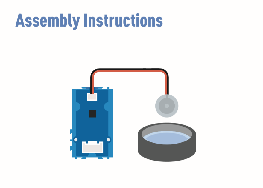
Assembly instructions
Arduino Instructions
Step 1. Follow the connection picture connect all the sensor on the board.
Step 2 Download the Aruidno IDE
Step 3 Navigate to Sketch -> Include Library -> Manage Libraries, search U8g2 then install it.
Step 4 Download the Grove_Temperature_And_Humidity_Sensor library and install it
Step 5. Copy the code stick on the Aruino IDE then upload it.
Step 6. Prepare a contain with full water then put the water atomization on the water.
Refer How to install library to install library for Arduino.
Prepare some tissue put on the water, let the water atomization keep afloat. The function of tissue is lead water to the transducer and keep upper side of transducer above water.
Code
#include <Arduino.h>
#include <U8x8lib.h>

#include "DHT.h"
#define DHTTYPE DHT11   // DHT 11
#define DHTPIN 3     // what pin we're connected to
DHT dht(DHTPIN, DHTTYPE);

#include <Wire.h>

U8X8_SSD1306_128X64_NONAME_HW_I2C u8x8(/* reset=*/ U8X8_PIN_NONE);

void setup(void) {
  Serial.begin(115200);
  u8x8.begin();
  u8x8.setFlipMode(1);
  Wire.begin();
  dht.begin();
  pinMode(2,INPUT);
}

void loop(void) {
  float temp_hum_val[2] = {0};
  int b;
  int c;
  if (!dht.readTempAndHumidity(temp_hum_val)) {
     b = temp_hum_val[0];
     c = temp_hum_val[1];
  }
  else{
    Serial.println("Failed to get temprature and humidity value.");
    }
  u8x8.setFont(u8x8_font_chroma48medium8_r);   // choose a suitable font
  u8x8.setCursor(0, 0);
  u8x8.print("Temp: ");
  u8x8.setCursor(5, 0);
  u8x8.print(c);
  u8x8.setCursor(8, 0);
  u8x8.print("*C");
  u8x8.setCursor(0, 10);
  u8x8.print("Hum: ");
  u8x8.setCursor(5, 10);
  u8x8.print(b);
  u8x8.setCursor(8, 10);
  u8x8.print("%");
  u8x8.setCursor(0, 20);
  u8x8.print("atomizer: ");

  if(b > 70){
  u8x8.setCursor(9, 20);
  u8x8.print("OFF");
  digitalWrite(2, LOW);    // atomization stopped
  }
  if(b <= 70) {
  u8x8.setCursor(9, 20);
  u8x8.print("ON ");
  digitalWrite(2, HIGH);   // atomize
    }
  delay(1000);

}
Project 5: Ultrasonic Radar
Overview
This wiki introduce how to make a Ultrasonic Radar to detect the object and distance.
Feature
-
Detect the object distance
-
Scan if exist the object in around
Component required
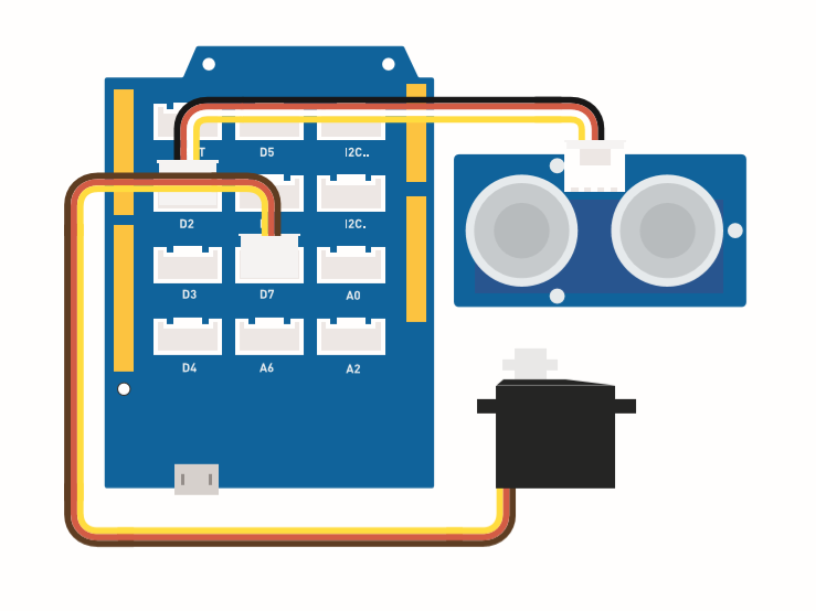
Hardware Connection
Please follow the picture, connect the ultrasonic sensor Grove cable to the D2, connect the servo to the D7.
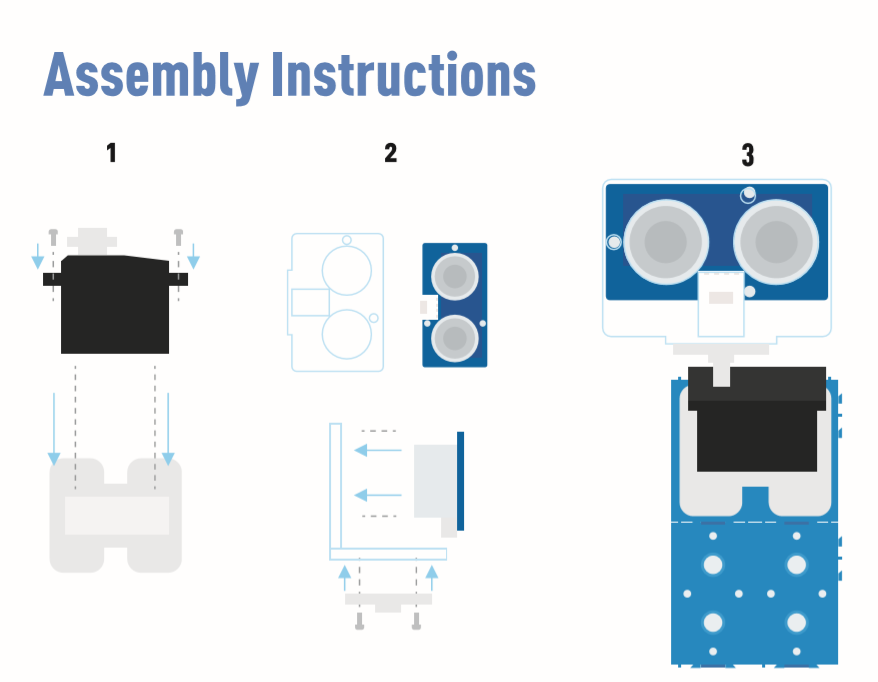
Assembly instuction
Arduino Instructions
Step 1. Follow the Connection to plug the cable on the port.
Step 2. Download the Aruidno IDE
Step 3. Download the Processing
Step 4. Download the UltrasonicRanger Library from Github.
Step 5. Copy the Radar code and stick on the Arduino IDE then upload it.
Step 6. Download the Processing for display the Radar scan map.
Step 7. Copy the Radar-Processing Code and stick on the Processing.
Step 8. After the Servo start swing, click play on the Processing software.
If you do not konw how to intall the library, Click here.
Radar code
#include <Servo.h>
#include "Ultrasonic.h"

int distance;
Servo myServo;

Ultrasonic ultrasonic(2);

void setup() {
    Serial.begin(9600);
    myServo.attach(7);
}
void loop() {

    for(int pos = 15; pos <= 165; pos += 1){
        myServo.write(pos);
        delay(30);
        distance = ultrasonic.MeasureInCentimeters();
        Serial.print(pos);
        Serial.print(",");
        Serial.print(distance);
        Serial.print(".");
    }

    for(int pos = 165; pos >= 15; pos -= 1){
        myServo.write(pos);
        delay(30);
        distance = ultrasonic.MeasureInCentimeters();
        Serial.print(pos);
        Serial.print(",");
        Serial.print(distance);
        Serial.print(".");
    }
}
Radar-Processing Code
import processing.serial.*; // imports library for serial communication
import java.awt.event.KeyEvent; // imports library for reading the data from the serial port
import java.io.IOException;
Serial myPort; // defines Object Serial
// defubes variables
String angle="";
String distance="";
String data="";
String noObject;
float pixsDistance;
int iAngle, iDistance;
int index1=0;
int index2=0;
PFont orcFont;
void setup() {

 size (1000, 720); // ***CHANGE THIS TO YOUR SCREEN RESOLUTION***
 smooth();
 myPort = new Serial(this,"COM14", 9600); // starts the serial communication
 myPort.bufferUntil('.'); // reads the data from the serial port up to the character '.'. So actually it reads this: angle,distance.
 orcFont = loadFont("AgencyFB-Bold-48.vlw");
}
void draw() {

  fill(98,245,31);
  textFont(orcFont);
  // simulating motion blur and slow fade of the moving line
  noStroke();
  fill(0,4);
  rect(0, 0, width, height-height*0.065);

  fill(98,245,31); // green color
  // calls the functions for drawing the radar
  drawRadar();
  drawLine();
  drawObject();
  drawText();
}
void serialEvent (Serial myPort) { // starts reading data from the Serial Port
  // reads the data from the Serial Port up to the character '.' and puts it into the String variable "data".
  data = myPort.readStringUntil('.');
  data = data.substring(0,data.length()-1);

  index1 = data.indexOf(","); // find the character ',' and puts it into the variable "index1"
  angle= data.substring(0, index1); // read the data from position "0" to position of the variable index1 or thats the value of the angle the Arduino Board sent into the Serial Port
  distance= data.substring(index1+1, data.length()); // read the data from position "index1" to the end of the data pr thats the value of the distance

  // converts the String variables into Integer
  iAngle = int(angle);
  iDistance = int(distance);
}
void drawRadar() {
  pushMatrix();
  translate(width/2,height-height*0.074); // moves the starting coordinats to new location
  noFill();
  strokeWeight(2);
  stroke(98,245,31);
  // draws the arc lines
  arc(0,0,(width-width*0.0625),(width-width*0.0625),PI,TWO_PI);
  arc(0,0,(width-width*0.27),(width-width*0.27),PI,TWO_PI);
  arc(0,0,(width-width*0.479),(width-width*0.479),PI,TWO_PI);
  arc(0,0,(width-width*0.687),(width-width*0.687),PI,TWO_PI);
  // draws the angle lines
  line(-width/2,0,width/2,0);
  line(0,0,(-width/2)*cos(radians(30)),(-width/2)*sin(radians(30)));
  line(0,0,(-width/2)*cos(radians(60)),(-width/2)*sin(radians(60)));
  line(0,0,(-width/2)*cos(radians(90)),(-width/2)*sin(radians(90)));
  line(0,0,(-width/2)*cos(radians(120)),(-width/2)*sin(radians(120)));
  line(0,0,(-width/2)*cos(radians(150)),(-width/2)*sin(radians(150)));
  line((-width/2)*cos(radians(30)),0,width/2,0);
  popMatrix();
}
void drawObject() {
  pushMatrix();
  translate(width/2,height-height*0.074); // moves the starting coordinats to new location
  strokeWeight(9);
  stroke(255,10,10); // red color
  pixsDistance = iDistance*((height-height*0.1666)*0.025); // covers the distance from the sensor from cm to pixels
  // limiting the range to 40 cms
  if(iDistance<40){
    // draws the object according to the angle and the distance
  line(pixsDistance*cos(radians(iAngle)),-pixsDistance*sin(radians(iAngle)),(width-width*0.505)*cos(radians(iAngle)),-(width-width*0.505)*sin(radians(iAngle)));
  }
  popMatrix();
}
void drawLine() {
  pushMatrix();
  strokeWeight(9);
  stroke(30,250,60);
  translate(width/2,height-height*0.074); // moves the starting coordinats to new location
  line(0,0,(height-height*0.12)*cos(radians(iAngle)),-(height-height*0.12)*sin(radians(iAngle))); // draws the line according to the angle
  popMatrix();
}
void drawText() { // draws the texts on the screen

  pushMatrix();
  if(iDistance>40) {
  noObject = "Out of Range";
  }
  else {
  noObject = "In Range";
  }
  fill(0,0,0);
  noStroke();
  rect(0, height-height*0.0648, width, height);
  fill(98,245,31);
  textSize(25);

  text("10cm",width-width*0.3854,height-height*0.0833);
  text("20cm",width-width*0.281,height-height*0.0833);
  text("30cm",width-width*0.177,height-height*0.0833);
  text("40cm",width-width*0.0729,height-height*0.0833);
  textSize(40);
  text("Object: " + noObject, width-width*0.875, height-height*0.0277);
  text("Angle: " + iAngle +" °", width-width*0.48, height-height*0.0277);
  text("Distance: ", width-width*0.26, height-height*0.0277);
  if(iDistance<40) {
  text("        " + iDistance +" cm", width-width*0.225, height-height*0.0277);
  }
  textSize(25);
  fill(98,245,60);
  translate((width-width*0.4994)+width/2*cos(radians(30)),(height-height*0.0907)-width/2*sin(radians(30)));
  rotate(-radians(-60));
  text("30°",0,0);
  resetMatrix();
  translate((width-width*0.503)+width/2*cos(radians(60)),(height-height*0.0888)-width/2*sin(radians(60)));
  rotate(-radians(-30));
  text("60°",0,0);
  resetMatrix();
  translate((width-width*0.507)+width/2*cos(radians(90)),(height-height*0.0833)-width/2*sin(radians(90)));
  rotate(radians(0));
  text("90°",0,0);
  resetMatrix();
  translate(width-width*0.513+width/2*cos(radians(120)),(height-height*0.07129)-width/2*sin(radians(120)));
  rotate(radians(-30));
  text("120°",0,0);
  resetMatrix();
  translate((width-width*0.5104)+width/2*cos(radians(150)),(height-height*0.0574)-width/2*sin(radians(150)));
  rotate(radians(-60));
  text("150°",0,0);
  popMatrix();
}