Arduino Programming with Seeed Studio XIAO ESP32C6
| Seeed Studio XIAO ESP32C6 |
|---|
 |
The Seeed Studio XIAO ESP32C6 is powered by the highly-integrated ESP32-C6 SoC, built on two 32-bit RISC-V processors, with a high-performance (HP) processor with running up to 160 MHz, and a low-power (LP) 32-bit RISC-V processor, which can be clocked up to 20 MHz. There are 512KB SRAM and 4 MB Flash on the chip, allowing for more programming space, and binging more possibilities to the IoT control scenarios.
Getting Started
Pinout Overview
Before we begin, let's review all the pins that the XIAO ESP32C6 has and its functions with the following schematic.
| XIAO ESP32C6/XIAO ESP32C6 indication diagram |
|---|
| XIAO ESP32C6/XIAO ESP32C6 Sense Pin List |
- 5V - This is 5v out from the USB port. You can also use this as a voltage input but you must have some sort of diode (schottky, signal, power) between your external power source and this pin with anode to battery, cathode to 5V pin.
- 3V3 - This is the regulated output from the onboard regulator. You can draw 700mA
- GND - Power/data/signal ground
Serial Communication
There are two methods for serial communication with the XIAO ESP32C6: software serial and hardware serial. Software serial is commonly used for flexibility, while hardware serial offers better performance.
Hardware Setup
- Connect the TX pin of the external device to the RX pin (
D7) of the XIAO ESP32C6. - Connect the RX pin of the external device to the TX pin (
D6) of the XIAO ESP32C6.
Code Examples
Software Serial
To use software serial, install the EspSoftwareSerial library.
Currently we recommend version 7.0.0 of the EspSoftwareSerial library. Other versions may have varying degrees of problems that prevent the soft serial port from working properly.
#include <SoftwareSerial.h>

SoftwareSerial mySerial(D7, D6); // RX, TX

void setup() {
  Serial.begin(9600);
  mySerial.begin(9600);
}

void loop() {
  if (mySerial.available()) {
    char data = mySerial.read();
    Serial.print("Received via software serial: ");
    Serial.println(data);
  }

  if (Serial.available()) {
    char data = Serial.read();
    mySerial.print("Received via hardware serial: ");
    mySerial.println(data);
  }
}
This example sets up software serial on pins D7 (RX) and D6 (TX) at 9600 baud. It monitors both the hardware serial (USB) and software serial ports, echoing received data between them.
Hardware Serial
The XIAO ESP32C6 features a hardware UART (UART0) for serial communication, corresponding to pins D7/D6.
#include <HardwareSerial.h>

HardwareSerial mySerial(0); // UART0 (Serial0)

void setup() {
  Serial.begin(9600);  // USB serial
  mySerial.begin(9600); // UART0
}

void loop() {
  if (Serial.available()) {
    char data = Serial.read();
    Serial.print("Received on USB: ");
    Serial.println(data);
  }

  if (mySerial.available()) {
    char data = mySerial.read();
    Serial.print("Received on UART0: ");
    Serial.println(data);
  }
}
This example uses the hardware UART0 (Serial0) for communication. It initializes both the USB serial and UART0, then monitors both ports for incoming data, printing received messages to the USB serial port.
Serial1 Usage
According to the above XIAO ESP32C6 Pin diagrams for specific parameters, we can observe that there are TX pin and RX pin. This is different from serial communication, but the usage is also very similar, except that a few parameters need to be added. So next, we will use the pins led out by the chip for serial communication.
Core Function that need to be include:
Serial1.begin(BAUD,SERIAL_8N1,RX_PIN,TX_PIN);-- enalbe Serial1,the function prototype :<Serial.Type>.begin(unsigned long baud, uint32_t config, int8_t rxPin, int8_t txPin);baud:baud rateconfig:Configuration bitrxPin:Receive PintxPin:Send Pin
It is worth nothing that if we use digital pin port to define,this place should be#define RX_PIN D7、#define TX_PIN D6,please refer to the pin diagrams of different XIAO Series for specific parameters.
Here is an example program:
#define RX_PIN D7
#define TX_PIN D6
#define BAUD 115200
void setup() {
Serial1.begin(BAUD,SERIAL_8N1,RX_PIN,TX_PIN);
}
void loop() {
if(Serial1.available() > 0)
{
char incominByte = Serial1.read();
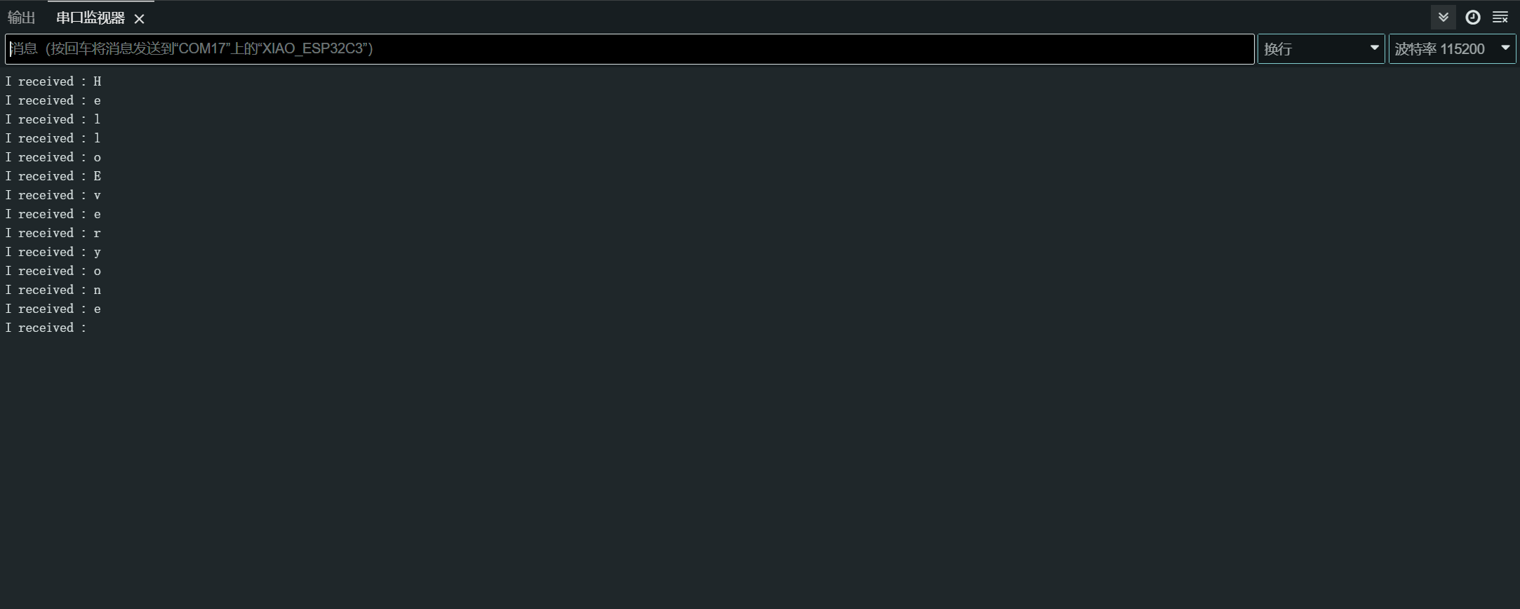
Serial1.print("I received : ");
Serial1.println(incominByte);
}
delay(1000);
}
After uploading the program, open the Serial Monitor in Arduino IDE and set the baud rate to 115200.then,you can send content you want in the XIAO ESP32C6 through the serial monitor Serial ,and XIAO will print out each byte of the content you send.,In here,the content i entered is "Hello Everyone",my result chart is as follows
Digital I/O
The XIAO ESP32C6 has 12 GPIO pins that you can configure as input or output.
Hardware Preparation
- Connect a button to pin
D1:- Use an external pull-up resistor (optional if using the internal pull-up resistor).
- Connect an LED to pin
D10:- Include a current-limiting resistor in series with the LED.
Software Implementation
The GPIO API provides functions to configure and interact with the GPIO pins. Refer to the GPIO API documentation for more details.
const int buttonPin = D1; // Button pin
const int ledPin = D10; // LED pin

void setup() {
  pinMode(ledPin, OUTPUT); // Set LED pin as output
  pinMode(buttonPin, INPUT); // Set button pin as input
  // If not using an external pull-up resistor
  pinMode(buttonPin, INPUT_PULLUP); // Enable internal pull-up resistor
}

void loop() {
  int buttonState = digitalRead(buttonPin); // Read button state
  digitalWrite(ledPin, buttonState); // Write button state to LED
}
Interrupt Method
You can also use interrupts to handle button presses more efficiently.
// Define the pin numbers for the button and LED
const int buttonPin = D1;
const int ledPin = D10;

// Define a structure to hold button-related data
struct Button {
    const uint8_t PIN; // Pin number for the button
    uint32_t numberKeyPresses; // Counter for the number of button presses
    bool pressed; // Flag to indicate if the button is currently pressed
};

// Create an instance of the Button structure for the button
Button my_button = {buttonPin, 0, false};

// Interrupt Service Routine (ISR) to handle button presses
void ARDUINO_ISR_ATTR isr(void* arg) {
    Button* s = static_cast<Button*>(arg); // Cast the argument to a Button pointer
    s->numberKeyPresses += 1; // Increment the number of button presses
    s->pressed = true; // Set the pressed flag
}

void setup() {
    Serial.begin(115200);
    pinMode(my_button.PIN, INPUT_PULLUP); // Set the button pin as input with internal pull-up resistor
    attachInterruptArg(my_button.PIN, isr, &my_button, FALLING); // Attach the ISR to the button pin, triggered on falling edge
}

void loop() {
    if (my_button.pressed) { // Check if the button is pressed
        Serial.printf("Button 1 has been pressed %lu times\n", my_button.numberKeyPresses); // Print the number of button presses
        my_button.pressed = false; // Reset the pressed flag
    }

    static uint32_t lastMillis = 0; // Variable to store the last time the interrupt was detached
    if (millis() - lastMillis > 10000) { // Check if 10 seconds have elapsed
        lastMillis = millis(); // Update the last detach time
        detachInterrupt(my_button.PIN); // Detach the interrupt from the button pin
    }
}
In this example, we use a Button structure to hold the button-related data, including the pin number, the number of key presses, and a flag to indicate if the button is currently pressed.
The isr function is an Interrupt Service Routine (ISR) that handles button presses. It increments the number of button presses and sets the pressed flag to true.
In the setup function, we initialize the serial communication, set the button pin as an input with an internal pull-up resistor, and attach the isr function to the button pin as an interrupt handler triggered on a falling edge (button press).
In the loop function, we check if the button is pressed. If it is, we print the number of button presses to the serial monitor and reset the pressed flag. Additionally, we include a section that detaches the interrupt from the button pin every 10 seconds, presumably to allow for other operations or to prevent unintended interrupts.
Okay, got it. Here is the rewritten and more comprehensible version:
ADC - Analog to Digital Converter
The XIAO ESP32C6 has several analog input pins that allow reading analog voltages.
Refer to the ADC API documentation for more details.
Hardware Setup
- Connect a potentiometer to pin A0, with one end connected to 3.3V and the other to GND.
Software Implementation
Here's an Arduino sketch that reads an analog value:
const int analogPin = A0;

void setup() {
  // Initialize serial communication at 115200 bits per second
  Serial.begin(115200);

  // Set the resolution to 12 bits (0-4095)
  analogReadResolution(12);
}

void loop() {
  // Read the analog value and millivolts for the analogPin
  int analogValue = analogRead(analogPin);
  int analogVolts = analogReadMilliVolts(analogPin);

  // Print the values to the Serial Monitor
  Serial.printf("ADC analog value = %d\n", analogValue);
  Serial.printf("ADC millivolts value = %d\n", analogVolts);

  delay(100); // Delay for clear reading from serial
}
This code reads the analog value from the specified pin and prints it, along with the millivolt value, to the Serial Monitor.
PWM Signal / LED Control
The XIAO ESP32-C6 has 6 LEDC channels that can generate independent waveforms, which can be used, for example, to drive RGB LED devices.
Refer to the LEDC API documentation for more details.
Hardware Setup
- Connect an LED to pin
D2with a current-limiting resistor in series.
Software Implementation
Here are Arduino sketches that demonstrate PWM output:
General PWM
const int ledPin = D2;

void setup() {
  pinMode(ledPin, OUTPUT);
}

void loop() {
  for (int dutyCycle = 0; dutyCycle <= 255; dutyCycle++) {
    analogWrite(ledPin, dutyCycle);
    delay(10);
  }
}
This code gradually increases the LED brightness using PWM.
LED Control
/*
 LEDC Software Fade

 This example shows how to software fade an LED
 using the ledcWrite function.

 Code adapted from the original Arduino Fade example:
 https://www.arduino.cc/en/Tutorial/Fade

 This example code is in the public domain.
 */

// Use 12-bit precision for the LEDC timer
#define LEDC_TIMER_12_BIT  12

// Use 5000 Hz as the LEDC base frequency
#define LEDC_BASE_FREQ     5000

// Fade LED PIN (replace with LED_BUILTIN constant for the built-in LED)
#define LED_PIN            D5

int brightness = 0;    // How bright the LED is
int fadeAmount = 5;    // How many points to fade the LED by

// Arduino-like analogWrite
// Value has to be between 0 and valueMax
void ledcAnalogWrite(uint8_t pin, uint32_t value, uint32_t valueMax = 255) {
  // Calculate duty, 4095 from 2 ^ 12 - 1
  uint32_t duty = (4095 / valueMax) * min(value, valueMax);

  // Write duty to LEDC
  ledcWrite(pin, duty);
}

void setup() {
  // Setup timer and attach timer to the LED pin
  ledcAttach(LED_PIN, LEDC_BASE_FREQ, LEDC_TIMER_12_BIT);
}

void loop() {
  // Set the brightness on the LEDC channel
  ledcAnalogWrite(LED_PIN, brightness);

  // Change the brightness for the next loop iteration
  brightness = brightness + fadeAmount;

  // Reverse the direction of the fading at the ends of the fade
  if (brightness <= 0 || brightness >= 255) {
    fadeAmount = -fadeAmount;
  }
  // Wait for 30 milliseconds to see the dimming effect
  delay(30);
}
This code demonstrates how to fade an LED using the ledcWrite function. The LED brightness gradually increases and decreases in a continuous loop.
I2C
The XIAO ESP32C6 has a hardware I2C interface for communicating with I2C devices.
Refer to the I2C API documentation for more details.
Hardware Preparation
- Connect the SDA pin of the I2C device to the SDA pin (
D4) of the XIAO. - Connect the SCL pin of the I2C device to the SCL pin (
D5) of the XIAO.
Software Implementation
Master Mode
Here's an Arduino sketch that demonstrates reading from an I2C sensor:
#include <Wire.h>

const int sensorAddress = 0x40;

void setup() {
  Wire.begin();
  Serial.begin(115200);
}

void loop() {
  Wire.beginTransmission(sensorAddress);
  Wire.write(0x01);  // Register address
  Wire.endTransmission();

  Wire.requestFrom(sensorAddress, 2);
  if (Wire.available() >= 2) {
    int data = Wire.read() << 8 | Wire.read();
    Serial.println(data);
  }

  delay(100);
}
This code reads a 16-bit value from register 0x01 of an I2C sensor.
Slave Mode
Here's an Arduino sketch that demonstrates using the XIAO ESP32C6 as an I2C slave device:
#include "Wire.h"

#define I2C_DEV_ADDR 0x55

uint32_t i = 0;

void onRequest() {
  Wire.print(i++);
  Wire.print(" Packets.");
  Serial.println("onRequest");
}

void onReceive(int len) {
  Serial.printf("onReceive[%d]: ", len);
  while (Wire.available()) {
    Serial.write(Wire.read());
  }
  Serial.println();
}

void setup() {
  Serial.begin(115200);
  Serial.setDebugOutput(true);
  Wire.onReceive(onReceive);
  Wire.onRequest(onRequest);
  Wire.begin((uint8_t)I2C_DEV_ADDR);

#if CONFIG_IDF_TARGET_ESP32
  char message[64];
  snprintf(message, 64, "%lu Packets.", i++);
  Wire.slaveWrite((uint8_t *)message, strlen(message));
#endif
}

void loop() {
  // Slave device code here
}
In this slave mode example, the XIAO ESP32C6 is configured as an I2C slave device with address 0x55. The onReceive callback function is called when the slave receives data from the master, and the onRequest callback function is called when the master requests data from the slave.
SPI
The XIAO ESP32C6 microcontroller board features a built-in SPI interface, facilitating fast data exchange with other SPI-compatible devices. This is particularly useful in projects that require quick communication between multiple devices.
- For detailed technical specifications, refer to the XIAO ESP32C6 Datasheet.
- Learn more about how to use the SPI interface with the XIAO ESP32C6 by consulting the SPI API Documentation.
Hardware Preparation
To connect your XIAO ESP32C6 to another SPI device, follow these steps:
- MOSI (Master Out Slave In): Connect the
MOSIpin of the SPI device to pinD10on the XIAO. - MISO (Master In Slave Out): Connect the
MISOpin of the SPI device to pinD9on the XIAO. - SCK (Serial Clock): Connect the
SCKpin of the SPI device to pinD8on the XIAO. - CS (Chip Select): Connect the
CSpin of the SPI device to a digital pin (for example,D3) on the XIAO.
MOSI -> D10
MISO -> D9
SCK -> D8
CS -> D3 (as an example)
Software Implementation
Below is a simplified Arduino sketch that demonstrates basic SPI communication with an SPI device using the XIAO ESP32C6. This sketch sends a command to the SPI device and reads back the response(reads back data from an SPI device).
#include <SPI.h>

const int csPin = 3;  // Use pin D3 for Chip Select (CS)

void setup() {
  // Initialize SPI communication
  SPI.begin();
  // Set the CS pin as an output
  pinMode(csPin, OUTPUT);
  // Set the CS pin high to indicate no active communication
  digitalWrite(csPin, HIGH);
}

void loop() {
  // Start communication with the device
  digitalWrite(csPin, LOW);
  SPI.transfer(0x01);  // Send a command to the device
  int data = SPI.transfer(0);  // Read the response
  digitalWrite(csPin, HIGH);  // End communication

  // Print the received data
  Serial.println(data);
  delay(100);  // Wait for a short period
}
Ensure the pin assignments in your sketch match the physical connections in your hardware setup. The above example uses predefined pin numbers based on the pin_arduino.h file for the XIAO ESP32-C6, with an additional definition for the CS pin.