Interfaces Usage
Introduction
The reComputer J401 carrier board supports NVIDIA Jetson Orin Nano/NX(Orin Nano 4GB/Orin Nano 8GB, Orin NX 8GB/Orin NX 16GB) bringing exceptional performance and being engineered to tackle tough edge computing tasks with ease. It's the perfect choice for developing industrial automation systems, building powerful AI applications, and more.
It features networking capability that is equipped with 1x Gigabit Ethernet port for fast networking. It also comes with 4x USB 3.2 Type-A (10Gbps) ports, 1x USB 2.0 Type-C port, and 1x CAN connector for versatile connectivity options. This extension board has been mounted with 1x M.2 Key M 2280 for SSD card(128GB NVMe 2280 SSD included) and 1x M.2 Key E slot for LTE wireless connectivity expansion.
In addition, there are multiple peripherals supported on the board. It can enable users to capture and display high-quality video content with 2x 15-pin MIPI-CSI and 1x HDMI 2.1 connector for camera and display connection. There also includes a 5V PWM FAN header, one RTC socket and 2-pin RTC header.
The board supports a wide input range of 9-19V DC, making it flexible to integrate into a variety of computing tasks. It maintains operation in the temperature range from -10°C to 60°C.
For more accesorries suggestion, please refer to Bundle Page of reComputer J401.
260 Pin SODIMM
The main function of 260 pin SODIMM is to connect your carrier board with NVIDIA Jetson Orin Nano 4GB/NVIDIA Jetson Orin Nano 8GB, NVIDIA Jetson Orin NX 8GB/NVIDIA Jetson Orin NX 16GB.
Connection Overview
If the connection is correct, when you connect your power adapter, you will see the power indicator light up.
M.2 Key M
M.2 Key M is a specification for the physical and electrical layout of an M.2 connector that supports high-speed data transfer using the PCIe (Peripheral Component Interconnect Express) interface. M.2 Key M connectors are commonly used for connecting solid-state drives (SSDs) and other high-performance expansion cards to a motherboard or other host device. The "Key M" designation refers to the specific pin configuration and keying of the M.2 connector, which determines the type of devices that can be connected to it.
Supported SSD are as follows
- 128GB NVMe M.2 PCle Gen3x4 2280 Internal SSD
- 256GB NVMe M.2 PCle Gen3x4 2280 Internal SSD
- 512GB NVMe M.2 PCle Gen3x4 2280 Internal SSD
- 1TB NVMe M.2 PCle Gen3x4 2280 Internal SSD
- 2TB NVMe M.2 PCle Gen3x4 2280 Internal SSD
Connection Overview
If you want to remove the included SSD and install a new one, you can follow the steps below.
Usage
We will explain how to do a simple benchmark on the connected SSD.
- Step 1: Check the write speed by executing the below command.
sudo dd if=/dev/zero of=/home/nvidia/test bs=1M count=512 conv=fdatasync
- Step 2: Check the read speed by executing the below commands. Make sure to execute this after executing the above command for write speed.
sudo sh -c "sync && echo 3 > /proc/sys/vm/drop_caches"
sudo dd if=/home/nvidia/test of=/dev/null bs=1M count=512
M.2 Key E
M.2 Key E is a specification for the physical and electrical layout of an M.2 connector that supports wireless communication modules, such as Wi-Fi and Bluetooth cards. The "Key E" designation refers to the specific pin configuration and keying of the M.2 connector, which is optimized for wireless networking devices. M.2 Key E connectors are commonly found on motherboards and other devices that require wireless connectivity options.Here we recommand Intel wifi/bluetooth module.
Connection Overview
Usage
After installing wifi/bluetooth module, you can see the wifi/bluetooth icon in the top right corner.
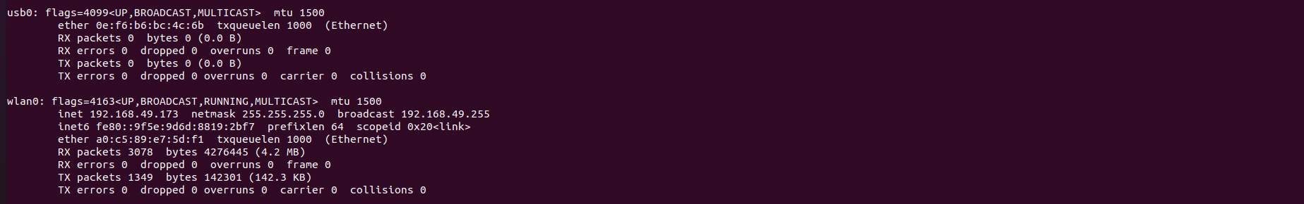
Wi-Fi test
ifconfig
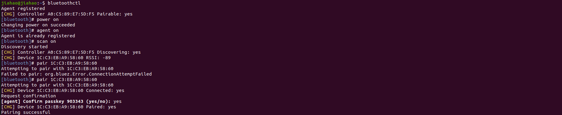
Bluetooth test
bluetoothctl
power on   #open bluetooth
agent on   #registe agent
scan on    #search other bluetooths
connect xx:xx:xx:xx #connect target bluetooth
paired-devices #show all paired devices
CSI Cameras
CSI stands for Camera Serial Interface. It is a specification that describes a serial communication interface for transferring video data from image sensors to a host processor. CSI is commonly used in mobile devices, cameras, and embedded systems to enable high-speed and efficient transfer of image and video data for processing and analysis.
Supported cameras are as follows
-
IMX219 cameras
-
IMX477 cameras
Connection Overview
Here the 2 CSI camera connectors are marked as CAM0 and CAM1. You can either connect one camera to any connector out of the 2 or connect 2 cameras to both the connectors at the same time.
Usage
Open your terminal(Ctrl+Alt+T) and input command like below:
sudo /opt/nvidia/jetson-io/jetson-io.py
- Method 1
- Method 2
For CAM0 port
nvgstcapture-1.0 sensor-id=0
For CAM1 port
nvgstcapture-1.0 sensor-id=1
If you want to change further settings of the camera, you can type "nvgstcapture-1.0 --help" to access all the configurable options available.
For CAM0 port
gst-launch-1.0 nvarguscamerasrc sensor-id=0 sensor-mode=0 ! 'video/x-raw(memory:NVMM),width=1920, height=1080, framerate=20/1, format=NV12' ! nvvidconv ! xvimagesink
For CAM1 port
gst-launch-1.0 nvarguscamerasrc sensor-id=1 sensor-mode=0 ! 'video/x-raw(memory:NVMM),width=1920, height=1080, framerate=20/1, format=NV12' ! nvvidconv ! xvimagesink
If you want to change further settings of the camera, you can update the arguments such as width, height, framerate, format, etc.
RTC
RTC stands for Real-Time Clock. It is a clock that keeps track of the current time and date independently of the main system clock. RTCs are commonly used in computers, embedded systems, and other electronic devices to maintain accurate timekeeping even when the device is powered off. They are often powered by a small battery to ensure continuous operation and retain time and date information during power cycles.
Connection Overview
- Method 1
- Method 2
Connect a 3V CR1220 coin cell battery to the RTC socket on the board as shown below. Make sure the positive (+) end of the battery is facing upwards.
Connect a 3V CR2302 coin cell battery with JST connector to the 2-pin 1.25mm JST socket on the board as shown below:
Usage
-
Step 1: Connect an RTC battery as mentioned above.
-
Step 2: Turn on reComputer Industrial.
-
Step 3: On the Ubuntu Desktop, click the drop-down menu at the top right corner, navigate to
Settings > Date & Time, connect to a network via an Ethernet cable and select Automatic Date & Time to obtain the date/ time automatically.
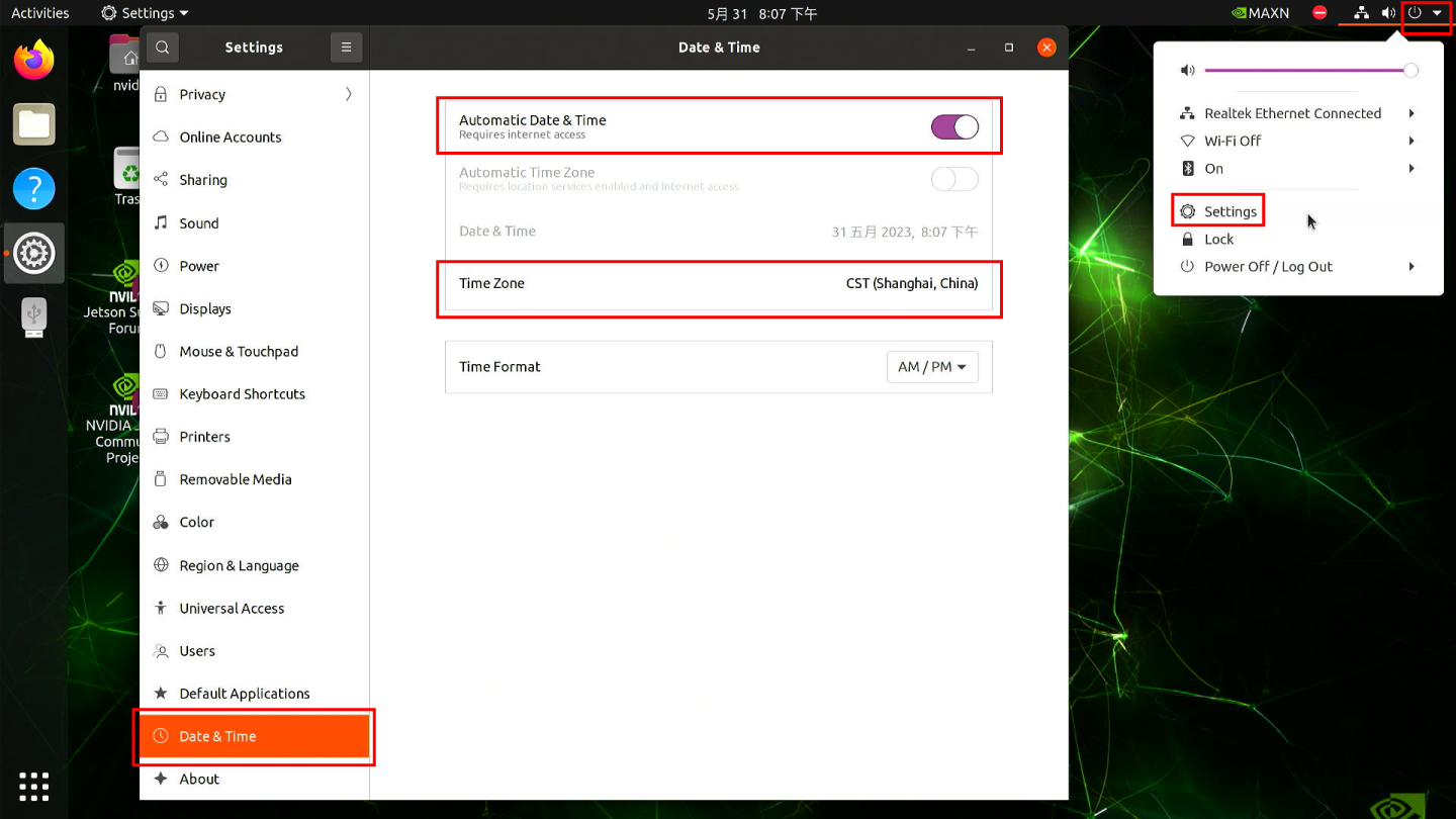
If you have not connected to internet via Ethernet, you can manually set the date/time here.
- Step 4: Open a terminal window, and execute the below command to check the hardware clock time.
sudo hwclock
You will see the output something like below which is not the correct date/time.

- Step 5: Change the hardware clock time to the current system clock time by entering the below command.
sudo hwclock --systohc
- Step 6: Remove any Ethernet cables connected to make sure it will not grab the time from the internet and reboot the board.
sudo reboot
-
Step 7: Check hardware clock time to verify that the date/ time stays the same eventhough the device was powered off.
-
Step 8: Create a new shell script using any text editor of your preference. Here we use vi text editor.
sudo vi /usr/bin/hwtosys.sh
- Step 9: Enter insert mode by pressing i, copy and paste the following content inside the file.
#!/bin/bash

sudo hwclock --hctosys
- Step 10: Make the script executable.
sudo chmod +x /usr/bin/hwtosys.sh
- Step 11: Create a systemd file.
sudo nano /lib/systemd/system/hwtosys.service
- Step 12: Add the following inside the file.
[Unit]
Description=Change system clock from hardware clock

[Service]
ExecStart=/usr/bin/hwtosys.sh

[Install]
WantedBy=multi-user.target
- Step 13: Reload systemctl daemon.
sudo systemctl daemon-reload
- Step 14: Enable the newly created service to start on boot and start the service.
sudo systemctl enable hwtosys.service
sudo systemctl start hwtosys.service
- Step 15: Verify the script is up and running as a systemd service.
sudo systemctl status hwtosys.service
- Step 16: Reboot the board and you will the system clock is now in sync with the hardware clock.
Fan control
nvfancontrol is a userspace fan speed control daemon. This manages the fan speed based on the temperature-to-fan-speed mapping table in the nvfancontrol configuration file.
There are some basic elements in the nvfancontrol service, including Tmargin, kickstart PWM, fan profile, fan control, and fan governor. All of these can be programmed via the configuration file based on the user’s preferences. This chapter will explain each of them in the following sections.
If you want to change nvfancontrol.conf make sure you have read it
Usage
- Method 1
- Method 2
- Step 1: Stop the nvfancontrol systemd service.
sudo systemctl stop nvfancontrol
- Step 2: Change nvfancontrol.conf.
vi /etc/nvfancontrol.conf
After you change nvfancontrol.conf, print Ese and :q to quit
- Step 3: Remove the status file.
sudo rm /var/lib/nvfancontrol/status
- Step 4: Restart nvfancontrol systemd service.
sudo systemctl restart nvfancontrol
- Step 1: Enter root model.
sudo -i
- Step 2: Stop the nvfancontrol systemd service.
sudo systemctl stop nvfancontrol
- Step 3: Change PWM value.
echo 100 > /sys/devices/platform/pwm-fan/hwmon/hwmon3/pwm1
The larger of value, the faster of fan speed. PWM value should between 0 to 255, maybe hwmon3 is not your pathword so check your own pathword
- Step 4: Check rpm.
cat /sys/class/hwmon/hwmon0/rpm
GPIO
The detail of 40-pin header is shown below:
| Header Pin | Module Pin Name | Module Pin | SoC Pin name | Default Usage | Alternate Functionality |
|---|---|---|---|---|---|
| 1 | - | - | - | Main 3.3V Supply | - |
| 2 | - | - | - | Main 5.0V Supply | - |
| 3 | I2C1_SDA | 191 | DP_AUX_CH3_N | I2C #1 Data | - |
| 4 | - | - | - | Main 5.0V Supply | - |
| 5 | I2C1_SCL | 189 | DP_AUX_CH3_P | I2C #1 Clock | - |
| 6 | - | - | - | Ground | - |
| 7 | GPIO09 | 211 | AUD_MCLK | GPIO | Audio Master Clock |
| 8 | UART1_TXD | 203 | UART1_TX | UART #1 Transmit | GPIO |
| 9 | - | - | - | Ground | - |
| 10 | UART1_RXD | 205 | UART1_RX | UART #1 Receive | GPIO |
| 11 | UART1_RTS* | 207 | UART1_RTS | GPIO | UART #2 Request to Send |
| 12 | I2S0_SCLK | 199 | DAP5_SCLK | GPIO | Audio I2S #0 Clock |
| 13 | SPI1_SCK | 106 | SPI3_SCK | GPIO | SPI #1 Shift Clock |
| 14 | - | - | - | Ground | - |
| 15 | GPIO12 | 218 | TOUCH_CLK | GPIO | - |
| 16 | SPI1_CSI1* | 112 | SPI3_CS1 | GPIO | SPI #1 Chip Select #1 |
| 17 | - | - | - | GPIO | - |
| 18 | SPI1_CSI0* | 110 | SPI3_CS0 | GPIO | SPI #0 Chip Select #0 |
| 19 | SPI0_MOSI | 89 | SPI1_MOSI | GPIO | SPI #0 Master Out/Slave In |
| 20 | - | - | - | Ground | - |
| 21 | SPI0_MISO | 93 | SPI1_MISO | GPIO | SPI #0 Master In/Slave Out |
| 22 | SPI1_MISO | 108 | SPI3_MISO | GPIO | SPI #1 Master In/Slave Out |
| 23 | SPI0_SCK | 91 | SPI1_SCK | GPIO | SPI #0 Shift Clock |
| 24 | SPI0_CS0* | 95 | SPI1_CS0 | GPIO | SPI #0 Chip Select #0 |
| 25 | - | - | - | Ground | - |
| 26 | SPI0_CS1* | 97 | SPI1_CS1 | GPIO | SPI #0 Chip Select #1 |
| 27 | I2C0_SDA | 187 | GEN2_I2C_SDA | I2C #0 Data | GPIO |
| 28 | I2C0_SCL | 185 | GEN2_I2C_SCL | I2C #0 Clock | GPIO |
| 29 | GPIO01 | 118 | SOC_GPIO41 | GPIO | General Purpose Clock #0 |
| 30 | - | - | - | Ground | - |
| 31 | GPIO11 | 216 | SOC_GPIO42 | GPIO | General Purpose Clock #1 |
| 32 | GPIO07 | 206 | SOC_GPIO44 | GPIO | PWM |
| 33 | GPIO13 | 228 | SOC_GPIO54 | GPIO | PWM |
| 34 | - | - | - | Ground | - |
| 35 | I2S0_FS | 197 | DAP5_FS | GPIO | Audio I2S #0 Field Select |
| 36 | UART1_CTS* | 209 | UART1_CTS | GPIO | UART #1 Clear to Send |
| 37 | SPI1_MOSI | 104 | SPI3_MOSI | GPIO | SPI #1 Master Out/Slave In |
| 38 | I2S0_DIN | 195 | DAP5_DIN | GPIO | Audio I2S #0 Data in |
| 39 | - | - | - | Ground | - |
| 40 | I2S0_DOUT | 193 | DAP5_DOUT | GPIO | Audio I2S #0 Data Out |
UART
UART stands for Universal Asynchronous Receiver/Transmitter. It is a communication protocol used for serial communication between two devices. UART communication involves two pins: one for transmitting data (TX) and one for receiving data (RX). It is asynchronous, meaning that data is transmitted without a shared clock signal between the devices. UART is commonly used in various applications such as microcontrollers, sensors, and communication between different electronic devices.
Connection Overview
The UART interface is using the pin below, or you can use another UART interface on J401:
| Header Pin | Module Pin Name | Module Pin | SoC Pin name | Default Usage | Alternate Funcationality |
|---|---|---|---|---|---|
| 6 | - | - | - | Ground | - |
| 8 | UART1_TXD | 203 | UART1_TX | UART #1 Transmit | GPIO |
| 10 | UART1_RXD | 205 | UART1_RX | UART #1 Receive | GPIO |
Connect the J401 with TTL with UART as below:
| J401 Header Pin | Usage | USB translate TTL | Usage |
|---|---|---|---|
| 6 | Ground | GND | Ground |
| 8 | UART1_TXD | U_RX | UART_RX |
| 10 | UART1_RXD | U_TX | UART_TX |
Usage
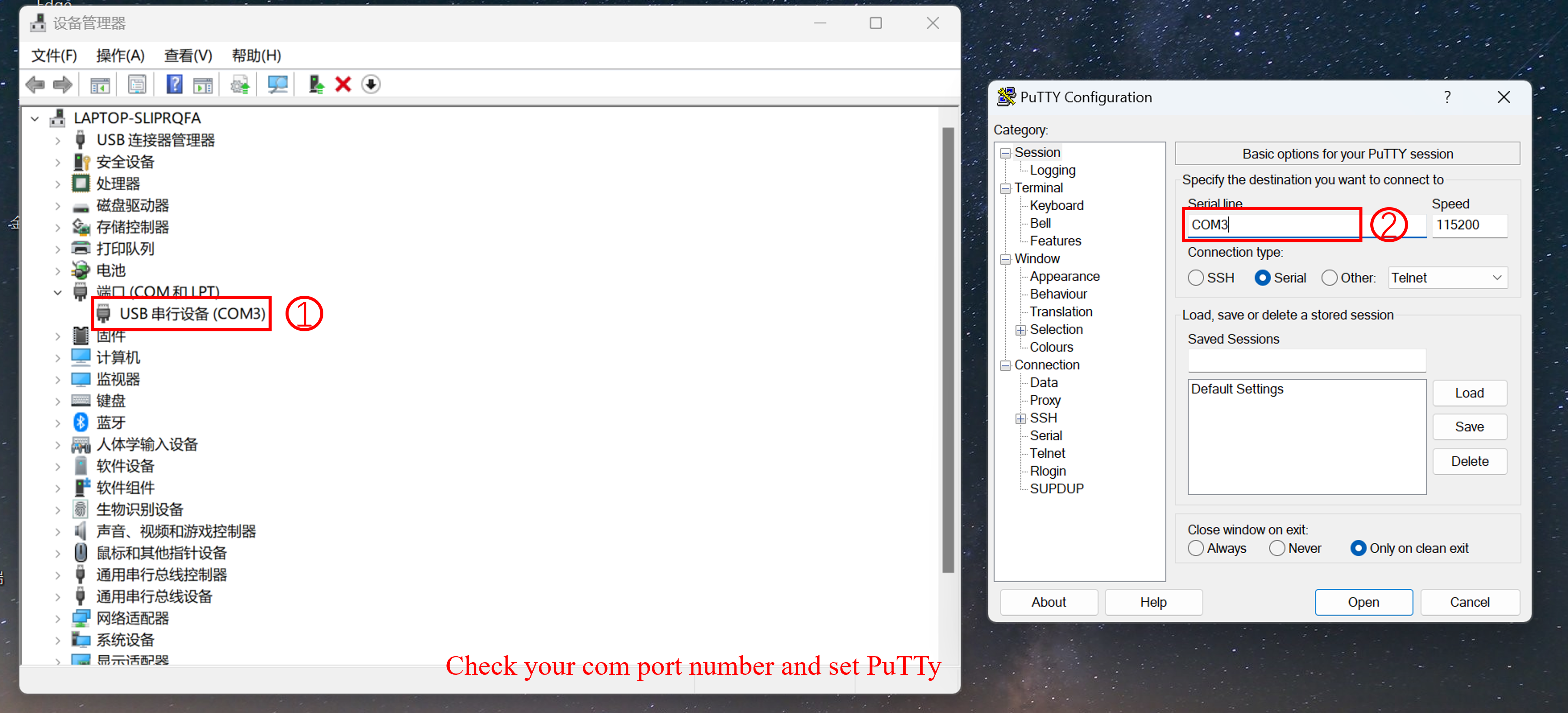
- Step 1: Install PuTTy on your windows laptop, and set PuTTy as below:
- Step 2: Install PuTTy on Jetson, open your terminal(ALT+Ctrl+T) and type the following command.
sudo apt install putty
- Step 3: Use PuTTy on Windows send 'hello linux' to Jetson, and use PuTTy on Jetson send 'hello windows' to windwos.
Make sure your baudrate have be set 115200.
The result is as below:
I2C
I2C stands for Inter-Integrated Circuit. It is a widely used serial communication protocol that enables communication between multiple integrated circuits in a system. I2C uses two bidirectional lines: one for data (SDA) and one for clock (SCL). Devices connected on an I2C bus can act as either a master or a slave, allowing for multiple devices to communicate with each other. I2C is popular for its simplicity, flexibility, and ability to connect a variety of devices such as sensors, memory chips, and other peripherals in embedded systems and electronic devices.
Connection Overview
The I2C interface is using pin as below, or you can use other I2C interface on J401:
| Header Pin | Module Pin Name | Module Pin | SoC Pin name | Default Usage | Alternate Funcationality |
|---|---|---|---|---|---|
| 2 | - | - | - | Main 5.0V Supply | - |
| 3 | I2C1_SDA | 191 | DP_AUX_CH3_N | I2C #1 Data | - |
| 5 | I2C1_SCL | 189 | DP_AUX_CH3_P | I2C #1 Clock | - |
| 6 | - | - | - | Ground | - |
Connect the J401 to Grove-3-Axis Digital Accelerometer with I2C as below:
| J401 | Usage | Grove-3-Axis Digital Accelerometer | Usage |
|---|---|---|---|
| 2 | 5V supply | Vcc | - |
| 3 | I2C1_SDA | SDA | I2C_SDA |
| 5 | I2C1_SCL | SCL | I2C_SCL |
| 6 | Ground | GND | Ground |
Test
Open your terminal(ALT+Ctrl+T) and type the following command:
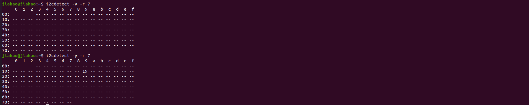
i2cdetect -y -r 7
Your channel may be different from mine in the commmand: i2cdetect -y -r x.
You will see the result as below, before connecting to the I2C, no I2C device was detected on channel 7, but afterwards an I2C device with the address 0x19 was detected.:
If you want to use general IO pins for logic control, please refer to this wiki.
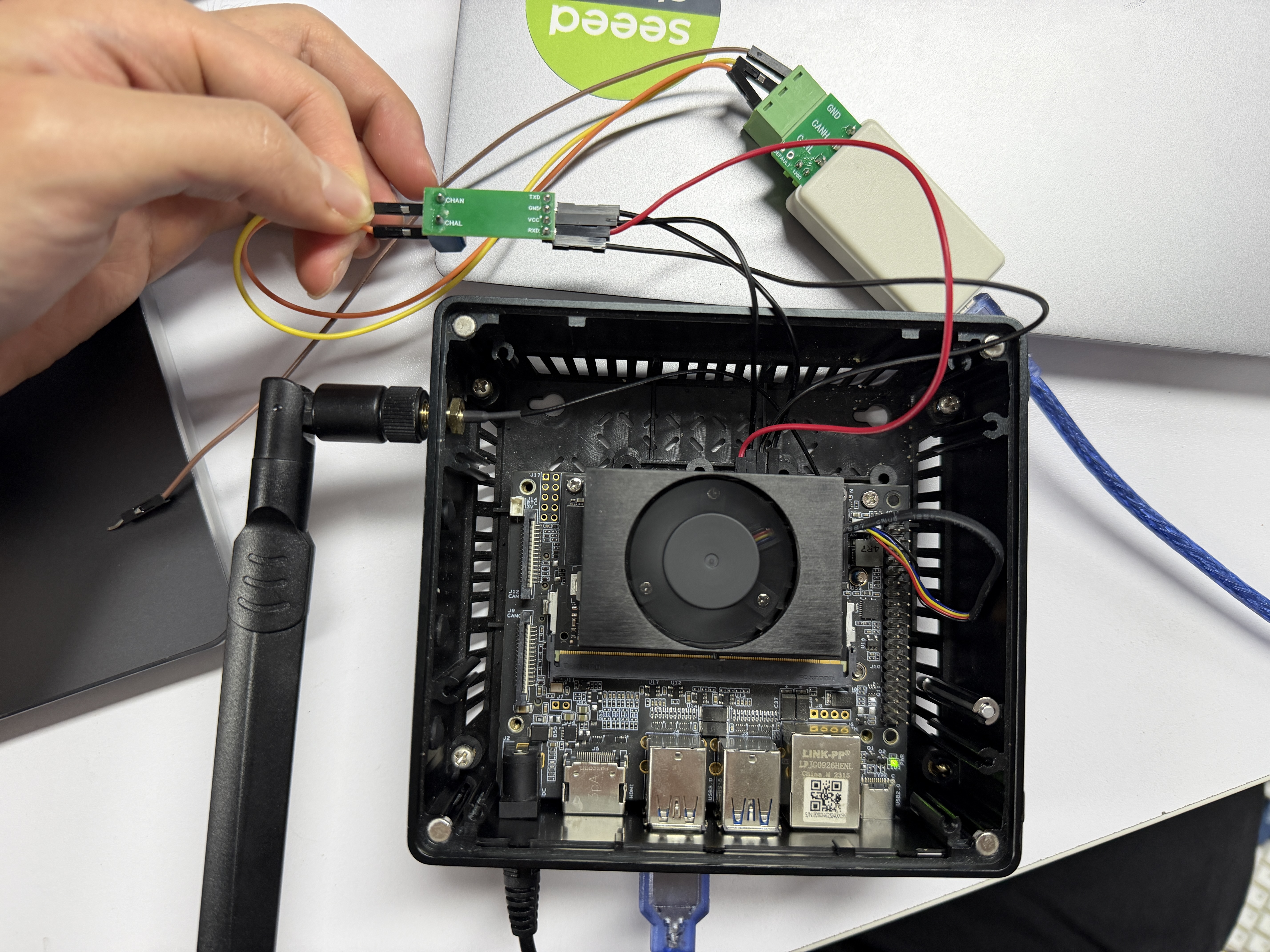
CAN
The reComputer J401 series provides a CAN interface where the CAN signal is output directly from the SOM at TTL/CMOS levels, which is a non-standard differential signal requiring an external CAN transceiver to connect to a standard CAN bus; it supports CAN FD frame formats, allowing extended data length and higher data rates, making it suitable for industrial automation, robotics, automotive prototyping, and other applications requiring reliable, real-time communication.
Connection Overview
Usage
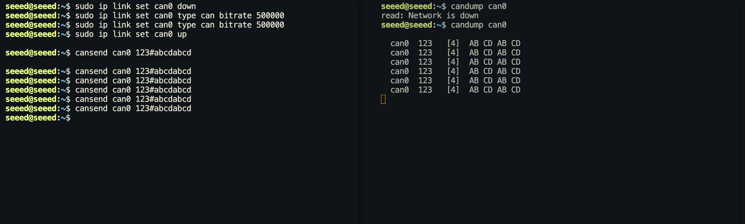
Step 1. Configure and open can0:
sudo ip link set can0 down
sudo ip link set can0 type can bitrate 500000
sudo ip link set can0 up
Step 2. Communication test. Open a terminal to receive signals.
candump can0
Step 3. Open another terminal to send the signal.
cansend can0 123#abcdabcd
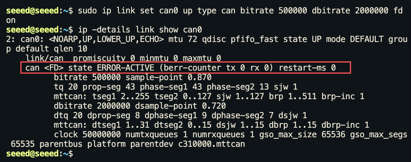
CAN FD
Step 1. Configure and open can0:
# Install can-utils Tools
sudo apt update && sudo apt install can-utils -y

# Enable CAN0 interface (FD mode, 5Mbps data segment rate)
sudo ip link set can0 up type can bitrate 500000 dbitrate 2000000 fd on
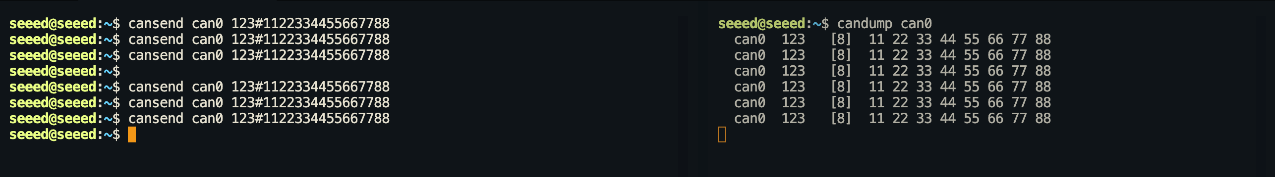
Step 2. Open another terminal to send the signal.
cansend can0 123#1122334455667788
Tech Support & Product Discussion
Thank you for choosing our products! We are here to provide you with different support to ensure that your experience with our products is as smooth as possible. We offer several communication channels to cater to different preferences and needs.