Seeed Studio XIAO SAMD21 with MicroPython
Introduction of MicroPython
MicroPython is a Python interprer with a partial native code compilation feature. It provides a subset of Python 3.5 features, implemented for embedded processors and constrained systems. It is different from CPython and you can read more about the differences here.

Getting Started
First, we are going to connect the Seeed Studio XIAO SAMD21 to the computer and upload a simple code from MicroPython to check whether the board is functioning well.
Hardware Setup
- Seeed Studio XIAO SAMD21 or Seeed Studio XIAO SAMD21 Plus x1
- Type-C cable x1
- PC x1
Flash the Firmware
For XIAO SAMD21
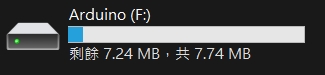
- Step 1. Connect the Seeed Studio XIAO SAMD21 to your computer via a Type‑C cable, then double‑tap the Reset button to enter BOOT mode. If it works well, there is an Arduino disk shown on the PC.
- Step 2. Flash the firmware
Just go to the MicroPython official and download the latest firmware
It is also possible to compile your own firmware in order to ensure security and support for the latest features, but this is not necessary.
For XIAO SAMD21 Plus
- Step 1. Connect the XIAO SAMD21 Plus to your PC with a Type‑C cable, then press the Reset button twice consecutively. If everything works correctly, an Arduino disk will appear on your PC.
-
Step 2. Click the link below to download the firmware, then drag‑and‑drop the
.uf2file into the Arduino disk to finish firmware flashing.
Software Setup
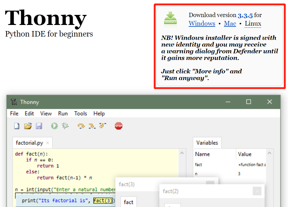
- Step 1. Download and Install the latest version of Thonny editor according to your operating system
-
Step 2. Launch the Thonny
-
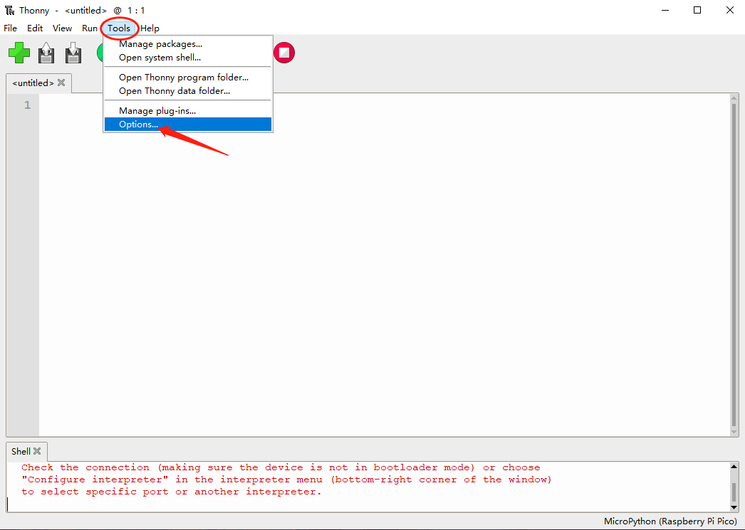
Step 3. Click Tools-->Options to open the settings.
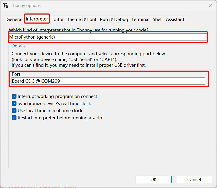
- Step 4. Chose the Interpreter interface and select the device as MicroPython(generic) and the port as Board CDC @ Port
Software Development
SEEED XIAO SAMD21 Series pin assignment table
| MicroPython Pin Name | XIAO SAMD21 GPIO (ID) | XIAO SAMD21 Plus GPIO (ID) | IRQ SAMD21 / Plus | ADC | Function |
|---|---|---|---|---|---|
| D0 / A0 | PA02 (2) | PA02 (2) | 2 / 2 | 0 | GPIO, ADC, DAC |
| D1 / A1 | PA04 (4) | PA04 (4) | 4 / 4 | 4 | GPIO, ADC |
| D2 / A2 | PA10 (10) | PA10 (10) | 10 / 10 | 18 | GPIO, ADC |
| D3 / A3 | PA11 (11) | PA11 (11) | 11 / 11 | 19 | GPIO, ADC |
| D4 / A4 / SDA | PA08 (8) | PA08 (8) | NMI / NMI | 16 | GPIO, ADC, I2C SDA |
| D5 / A5 / SCL | PA09 (9) | PA09 (9) | 9 / 9 | 17 | GPIO, ADC, I2C SCL |
| D6 / A6 / TX | PB08 (40) | PB08 (40) | 8 / 8 | 2 | GPIO, ADC, UART TX |
| D7 / A7 / RX | PB09 (41) | PB09 (41) | 9 / 9 | 3 | GPIO, ADC, UART RX |
| D8 / A8 / SCK | PA07 (7) | PA07 (7) | 7 / 7 | 7 | GPIO, ADC, SPI SCK |
| D9 / A9 / MISO | PA05 (5) | PA05 (5) | 5 / 5 | 5 | GPIO, ADC, SPI MISO |
| D10 / A10 / MOSI | PA06 (6) | PA06 (6) | 6 / 6 | 6 | GPIO, ADC, SPI MOSI |
| USER_LED / D13 / SCL1 | PA17 (17) | PA17 (17) | 1 / 1 | — | Original user LED; Plus D13 & I2C1 SCL |
| RX_LED / D27 | PA18 (18) | PA18 (18) | 2 / 2 | — | Original RX LED; Plus D27 |
| TX_LED / D19 / I2S_SD | PA19 (19) | PA19 (19) | 3 / 3 | — | Original TX LED; Plus D19 & I2S data |
| D12 | — | PA28 (28) | — / 8 | — | Plus expansion GPIO |
| D14 / SDA1 | — | PA16 (16) | — / 0 | — | Plus I2C1 SDA |
| D15 | — | PA15 (15) | — / 15 | — | Plus expansion GPIO |
| D16 | — | PA14 (14) | — / 14 | — | Plus expansion GPIO |
| D17 | — | PA13 (13) | — / 13 | — | Plus expansion GPIO |
| D18 | — | PA12 (12) | — / 12 | — | Plus expansion GPIO |
| D20 / I2S_SCK | — | PA20 (20) | — / 4 | — | Plus GPIO & I2S clock |
| D21 / I2S_WS | — | PA21 (21) | — / 5 | — | Plus GPIO & I2S word select |
| D22 | — | PB10 (42) | — / 10 | — | Plus expansion GPIO |
| D23 | — | PB11 (43) | — / 11 | — | Plus expansion GPIO |
| D24 | — | PB23 (55) | — / 7 | — | Plus expansion GPIO |
| D25 | — | PA23 (23) | — / 7 | — | Plus expansion GPIO |
| D26 | — | PA22 (22) | — / 6 | — | Plus expansion GPIO |
| RGB_LED | — | PA27 (27) | — / 15 | — | Plus addressable RGB LED (WS2812) |
| BUTTON | — | PB22 (54) | — / 6 | — | Plus user button (active low) |
| USB_DM | PA24 (24) | PA24 (24) | 12 / 12 | — | USB D− (native USB, not GPIO) |
| USB_DP | PA25 (25) | PA25 (25) | 13 / 13 | — | USB D+ (native USB, not GPIO) |
| SWCLK | PA30 (30) | PA30 (30) | 10 / 10 | — | SWD clock |
| SWDIO | PA31 (31) | PA31 (31) | 11 / 11 | — | SWD data |
The number inside parentheses in GPIO (ID) refers to the MicroPython SAMD Pin ID, not the physical MCU package pin number.
Upload your code
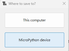
Upload the codes by clicking the "Run current script" button. For the first time, Thonny will ask where you want to save your codes file. Both This Computer and MicroPython device are fine.
If you want to use the program offline, you should save the program to XIAO SAMD21
Press and hold Ctrl + Shift + S at the same time , then select save to MicroPython device
GPIO TEST (LED)
We need to prepare:
-
Copy the following codes to Thonny.
-
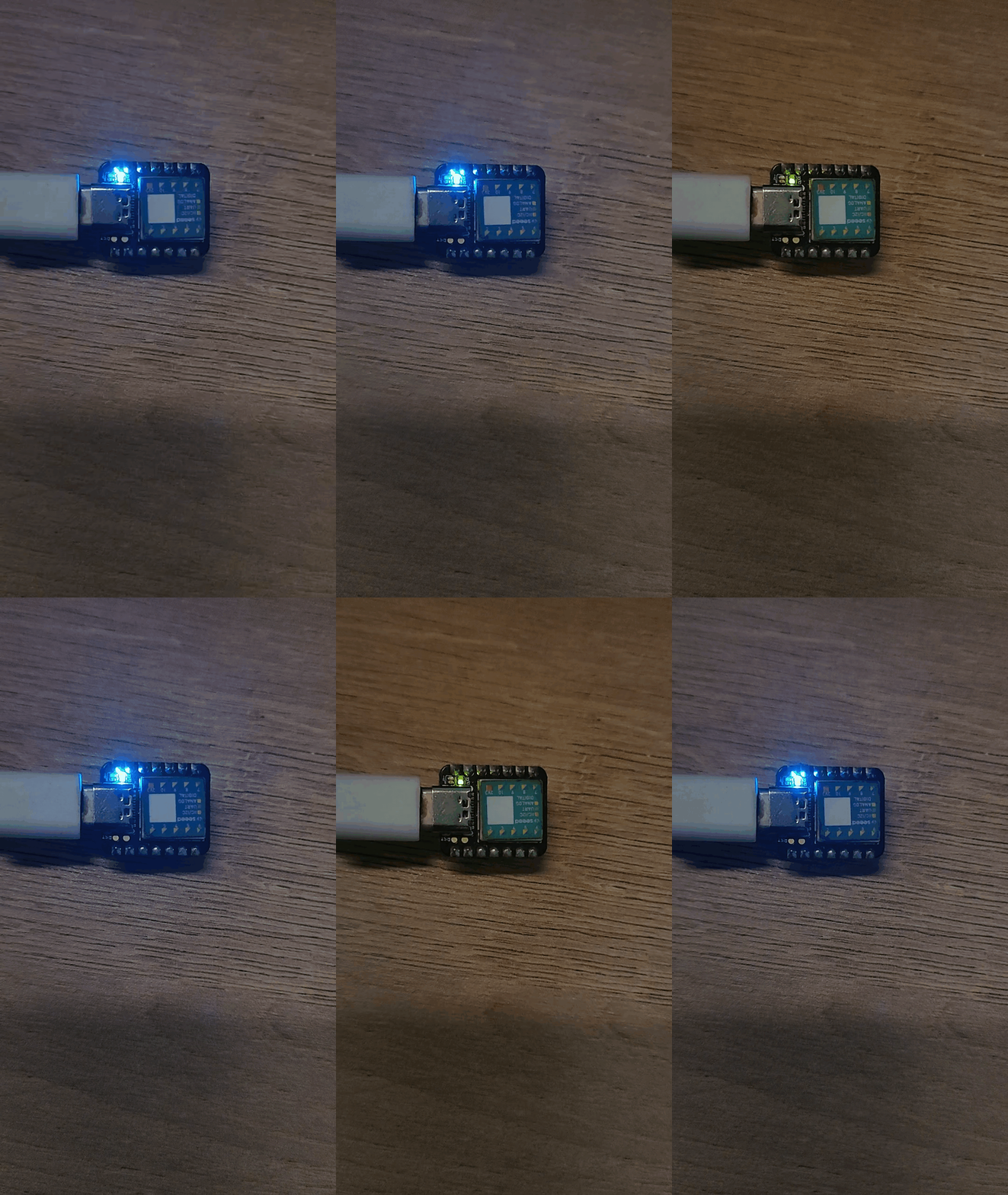
For XIAO SAMD21 , The RX_LED is PA18
We can see that the blue RX_LED is lit up and blinks once per second
from machine import Pin, Timer

led = Pin(18, Pin.OUT)
Counter = 0
Fun_Num = 0

def fun(tim):
    global Counter
    Counter = Counter + 1
    print(Counter)
    led.value(Counter%2)

tim = Timer(-1)
tim.init(period=500, mode=Timer.PERIODIC, callback=fun)
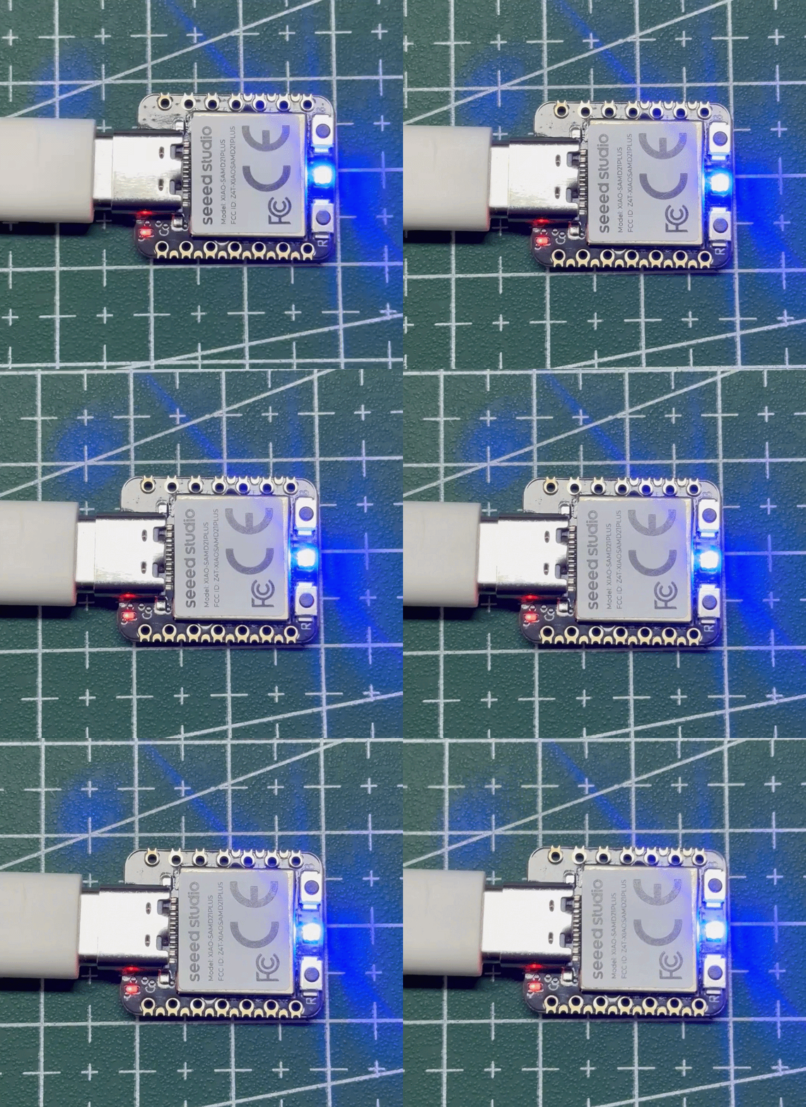
- For XIAO SAMD21 Plus, the RX_LED and TX_LED have been removed. A WS2812 LED is used instead, with its data pin assigned to PA27.
from machine import Pin, Timer
import machine
import time

led = Pin(27, Pin.OUT)

Counter = 0


def ws2812_write(r, g, b):
    data = bytearray([g, r, b])

    machine.bitstream(
        led,
        0,
        (400, 850, 800, 450),
        data
    )

    time.sleep_us(80)


def fun(tim):
    global Counter

    Counter += 1
    print(Counter)

    if Counter % 2 == 1:
        ws2812_write(0, 0, 255)
    else:
        ws2812_write(0, 0, 0)


# Initial state: OFF
ws2812_write(0, 0, 0)

# 500 ms periodic timer
tim = Timer(-1)
tim.init(
    period=500,
    mode=Timer.PERIODIC,
    callback=fun
)
GPIO Control Relays
We need to prepare:
from machine import Pin, Timer

output_4 = Pin(8, Pin.OUT)
detect_1 = Pin(4, Pin.IN, Pin.PULL_UP)
output_value = Pin(2, Pin.OUT)
Counter = 0

def fun(tim):
    global Counter
    Counter = Counter + 1
    output_4.value(Counter%2)
    print(Counter%2,detect_1.value())
    if detect_1.value() :
        output_value.value(1)
    else:
        output_value.value(0)

tim = Timer(-1)
tim.init(period=200, mode=Timer.PERIODIC, callback=fun)
Human detection for automatic control
We need to prepare:
- Doppler radar for human detection
- Seeeduino-XIAO-Expansion-Board
- Grove-Relay
- Seeed Studio XIAO SAMD21
from machine import Pin, Timer

led = Pin(8, Pin.OUT)

input_value_1 = Pin(4, Pin.IN, Pin.PULL_UP)
input_value_2 = Pin(10, Pin.IN, Pin.PULL_UP)
output_value = Pin(2, Pin.OUT)

Counter = 0
Fun_Num = 0

def fun(tim):
    global Counter
    Counter = Counter + 1
    led.value(Counter%2)
    print(input_value_1.value(),input_value_2.value())
    if input_value_1.value() :
        output_value.value(1)
    else:
        output_value.value(0)

tim = Timer(-1)
tim.init(period=50, mode=Timer.PERIODIC, callback=fun)
I2C Support
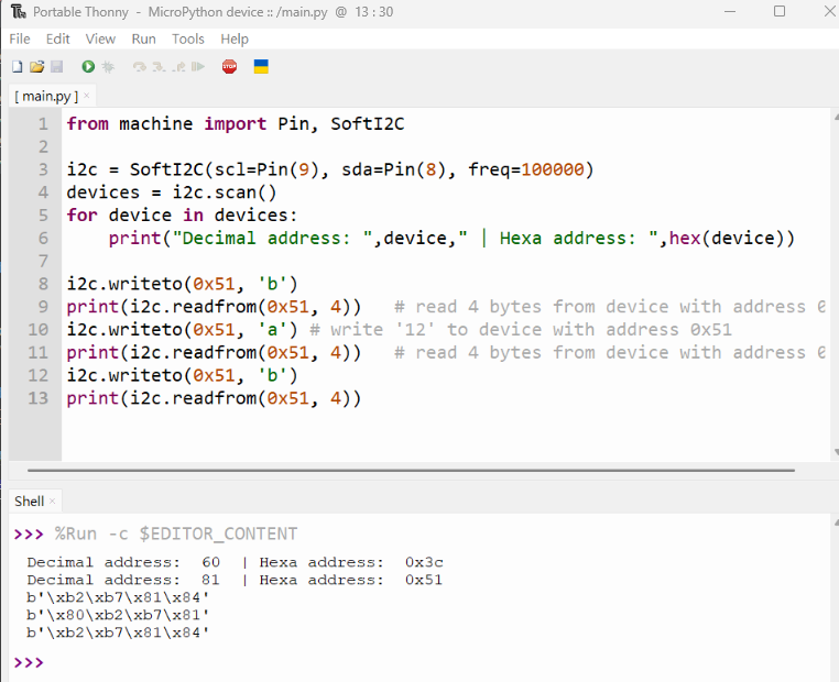
from machine import Pin, SoftI2C

i2c = SoftI2C(scl=Pin(9), sda=Pin(8), freq=100000)
devices = i2c.scan()
for device in devices:
    print("Decimal address: ",device," | Hexa address: ",hex(device))

i2c.writeto(0x51, 'b')
print(i2c.readfrom(0x51, 4))   # read 4 bytes from device with address 0x51
i2c.writeto(0x51, 'a') # write 'a' to device with address 0x51
print(i2c.readfrom(0x51, 4))   # read 4 bytes from device with address 0x51
i2c.writeto(0x51, 'b')
print(i2c.readfrom(0x51, 4))
Familiarity with micropython allows you to do more , we are looking forward to creating more value for you. Feel free to share your projects with us too!
DAC Support
Thank you to Aleksei Tertychnyi for submitting the code, all related functionalities were developed and contributed by him.
from machine import Pin, Timer, DAC

led = Pin(18, Pin.OUT)
counter = 0

dac = DAC(0) #DAC on A0 output

def loop(tim):
    global counter
    led.value(counter%2)
    print('DAC value: ', end =" ")
    print(counter)
    dac.write(counter%1024)
    counter = counter + 1

tim = Timer(-1)
tim.init(period=1000, mode=Timer.PERIODIC, callback=loop)
Voltage on pin A0 will start to gradually increase, after reaching maximum at appoximately 3.3V, will drop to 0V and cycle will repeat.
ADC Support
ADC example MicroPython code:
from machine import Pin, Timer, ADC
led = Pin(18, Pin.OUT)  # digital output for blinking
counter = 0             # simple counter for LED toggle

ADC_CONVERT_V = 1.0 / 65535.0  # conversion factor: raw ADC (16-bit) → voltage (vref=1.0V)

adc = ADC(4, vref=0)   # ADC reads on pin A4, using internal 1.0V reference
adcVoltage = 0.0       # variable to store measured voltage

def fun(tim):
    global counter, adcVoltage  # make sure we update the global variables
    counter += 1                # increment counter
    adcVoltage = adc.read_u16() * ADC_CONVERT_V  # read ADC and convert to voltage
    print(adcVoltage)           # print voltage to REPL
    led.value(counter % 2)      # toggle LED every callback (blink)

tim = Timer(-1)                    # create a virtual timer
tim.init(period=1000,              # callback period in milliseconds (1000 ms = 1 s)
         mode=Timer.PERIODIC,      # periodic callback
         callback=fun)             # function to call
MicroPython Device Console
Our partner Neil has written a command line console program for XIAO using MicroPython. With this programme you can easily upload, download and delete files. We thank him for his contribution to XIAO!
Tech Support & Product Discussion
Thank you for choosing our products! We are here to provide you with different support to ensure that your experience with our products is as smooth as possible. We offer several communication channels to cater to different preferences and needs.