Seeed Studio XIAO ESP32C6 with CircuitPython
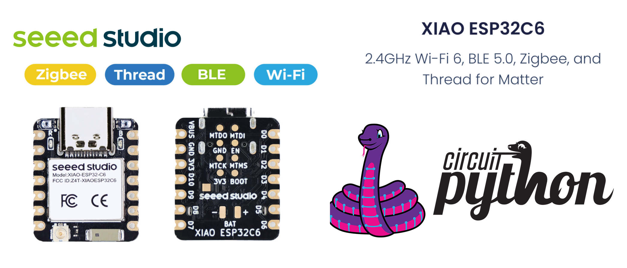
This wiki introduce how to install and run the official CircuitPython by Adafruit Industries on the Seeed Studio XIAO ESP32C6 development board! CircuitPython is a programming language designed to simplify experimenting and learning to program on low-cost microcontroller boards. It makes getting started easier than ever with no upfront desktop downloads needed. Once you get your board set up, open any text editor, and get started editing code. For more info, please refer to here.
Installing CircuitPython
Method 1: Command line esptool
Install Esptool
If you haven't already installed esptool.py, you can do so using pip on your pc:
pip install esptool
Download the ESP32C6 CircuitPython firmware
You need to download the firmware binary file from circirtpython.org After downloading correct bin file, navigate to the folder, and open a cmd terminal there. As of the final draft, the latest version of bin file is:
adafruit-circuitpython-seeed_xiao_esp32c6-en_GB-9.1.1.bin
Connect the XIAO ESP32C6 on your PC
You need to press and hold down BOOT button on your XIAO ESP32C6 board to enter the 'bootloader' mode while pluging in to the type C USB cable to your pc.
Check port
Find out all serial devices on your pc.
- Linux
On Linux, you can use the dmesg command to view connected devices:
dmesg | grep tty
Alternatively, you can list serial devices using ls:
ls /dev/ttyS* /dev/ttyUSB*
- Window
On Windows, you can check serial ports through Device Manager. Look for the “Ports (COM & LPT)” section to see the available serial ports. You can also use the mode command in Command Prompt to list serial ports:
mode
- macOS
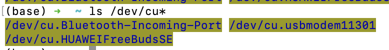
On macOS, you can list available serial ports using the ls command:
ls /dev/cu*
This will show all serial port devices.
If the port is busy, you can use the following command to find an dkill and processes using the port(On macOS): Identify processes using the port:
lsof | grep port
This command lists open files and searches for any process using the specified port. Find the process ID(PID) from the output and kill the procee:
kill -9 <PID>
Replace PID with the actual process ID found.
Erase flash
esptool.py --chip esp32c6 --port /dev/cu.usbmodem11301 erase_flash
Replace '/dev/cu.usbmodem11301' with the correct port name from your system(e.g. COM3 on Windows, /dev/ttyUSB0 on linux).
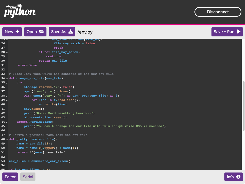
Write flash
Flash the firmware onto XIAO ESP32C6:
esptool.py --chip esp32c6 --port /dev/cu.usbmodem11301 --baud 460800 write_flash -z 0x0 adafruit-circuitpython-seeed_xiao_esp32c6-en_GB-9.1.1.bin
Again, replace '/dev/cu.usbmodem11301' with the correct port name, and 'adafruit-circuitpython-seeed_xiao_esp32c6-en_GB-9.1.1.bin' with the path to your blank firmware file. Hard resetting via RTS pin...
Method 2: Web Serial esptool
The WebSerial ESPTool was designed to be a web-capable option for programming Espressif ESP family microcontroller boards that have a serial based ROM bootloader. It allows you to erase the contents of the microcontroller and program up to 4 files at different offsets. Please refer to Web Serial ESPtool.
Then can start to compile script using your prefer tool to ESP32C6!
Recommended Editors for CircuitPython
Generally, When CircuitPython finishes installing, or you plug a CircuitPython board into your computer with CircuitPython already installed, the board shows up on your computer as a USB drive called CIRCUITPY. However, ESP32 / ESP32-C3 / ESP32-C6 microcontrollers that do not support native USB cannot present a CIRCUITPY drive. On these boards, there are alternative ways to transfer and edit files. You can use the Thonny, which uses hidden commands sent to the REPL to read and write files. Or you can use the CircuitPython web workflow, introduced in Circuitpython 8. The web workflow provides browser-based WiFi access to the CircuitPython filesystem, please refer to getting started with web workflow using the code editor
1. Thonny
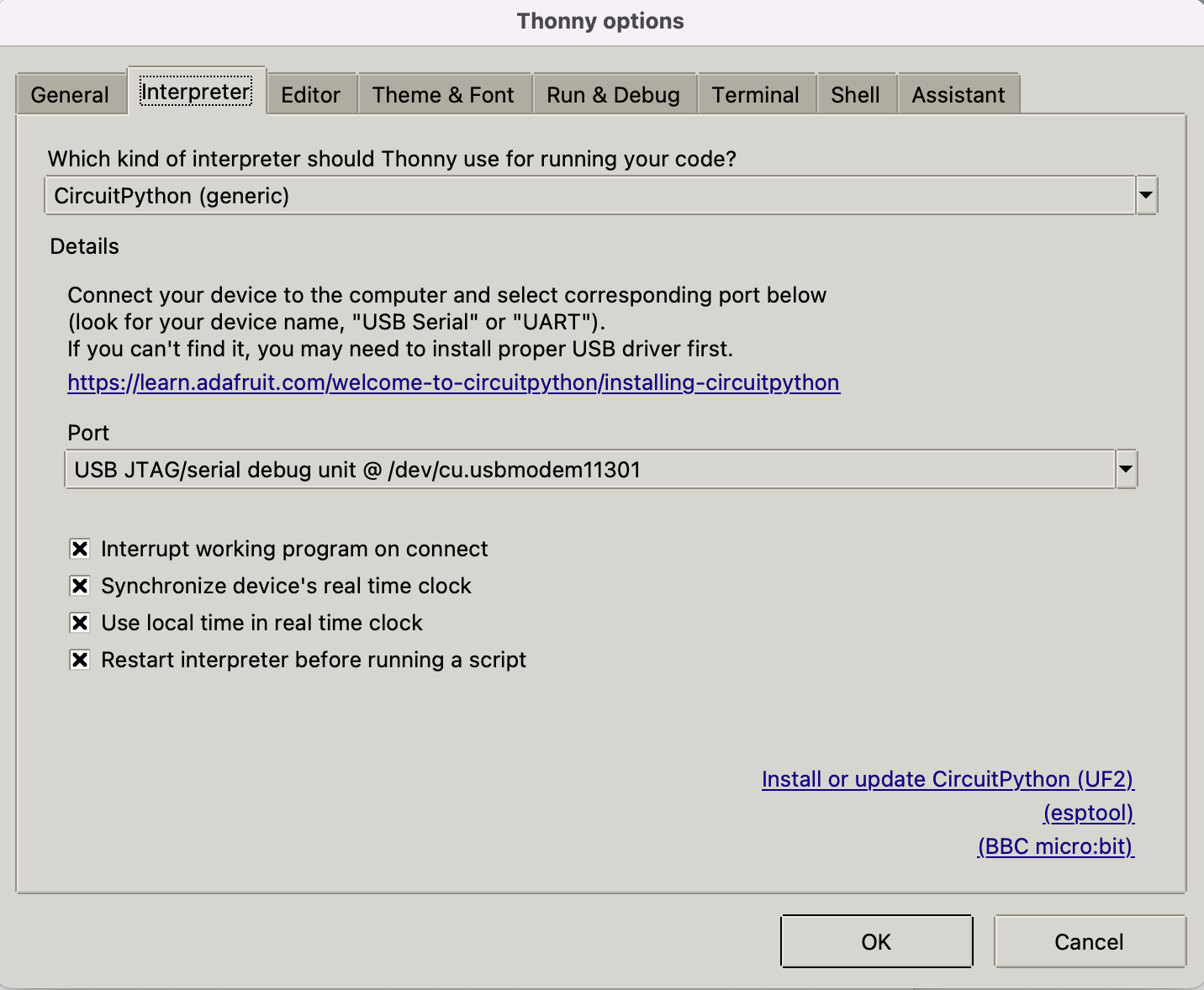
Install and open thonny, then configure Thonny following the instruction:
pip install thonny
#open thonny after installation
thonny
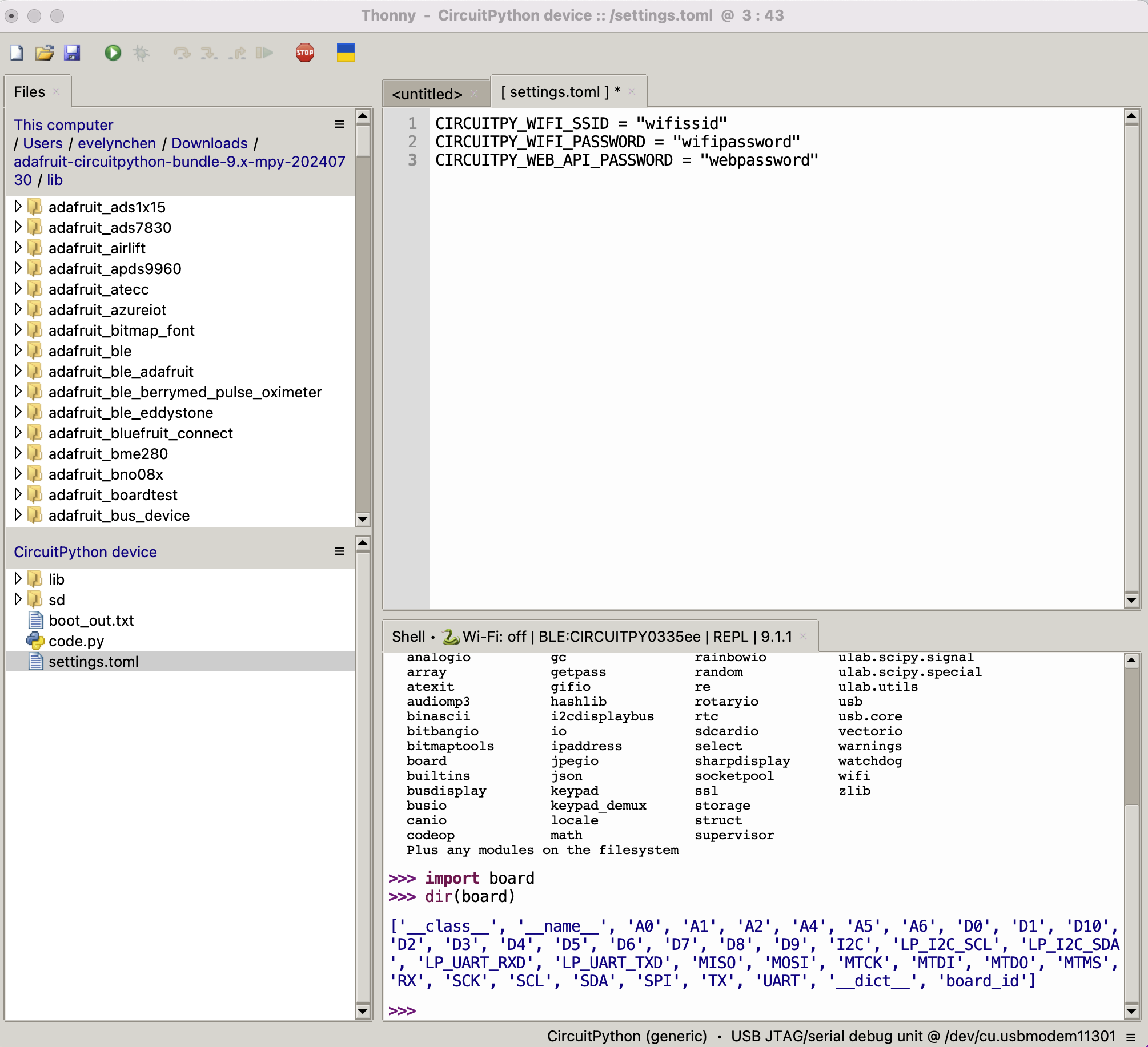
Go to Run-->Configure Interpreter, and ensure that the Interpreter tab in the Thonny options looks as shown below, select "CircuitPython (generic)" and port:
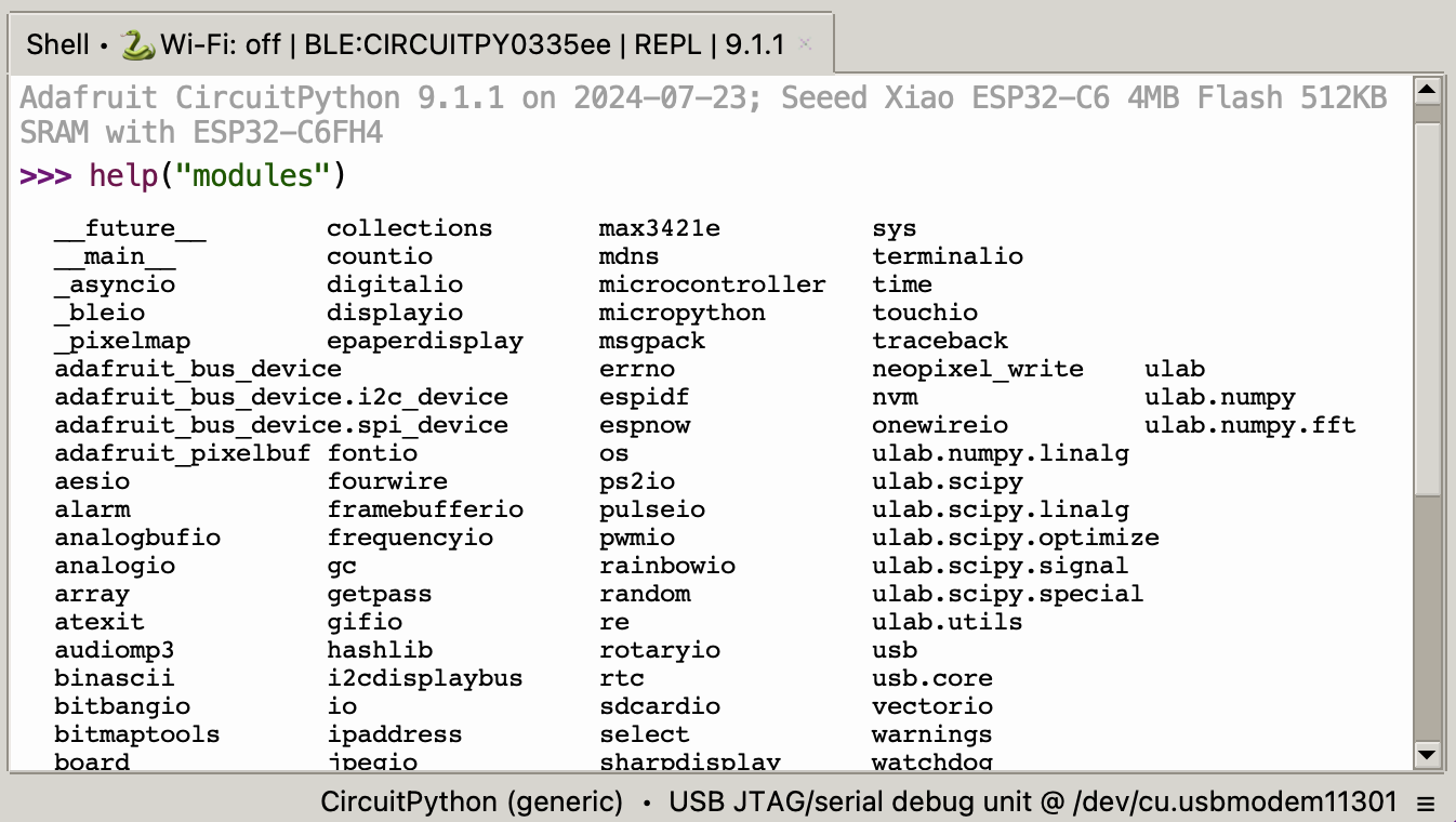
click "OK" on the dialog and you should be presented with the Micropython shell at the bottom of the thonny window as shown in the figure below. Then you can use Read-Evaluate-Print-Loop, or REPL for serial connection, which allows you to enter individual lines of code and have them run immediately in the shell. It's really handy if you're running into trouble with a particular program and can't figure out why. It's interactive so it's great for testing new ideas. Please refer to REPL for more information.
Interacting with the REPL with help(), which tell you where to start exploring the REPL. To run code in REPL, type it in next to the REPL prompt. To list built-in modules type help("modules") and would show up a list of all the core modules built into CircuitPython, including "board".
Then can type "import board" into the REPL and press enter. Next, type "dir(board)" into the REPL and get a list of all of the pins on your board.
#check pin using following command.For details on REPL, see Welcome to CircuitPython!
#enter to the shell of Thonny.
>>> import board
>>> dir(board)
['__class__', '__name__', 'A0', 'A1', 'A2', 'A4', 'A5', 'A6', 'D0', 'D1', 'D10', 'D2', 'D3', 'D4', 'D5', 'D6', 'D7', 'D8', 'D9', 'I2C', 'LP_I2C_SCL', 'LP_I2C_SDA', 'LP_UART_RXD', 'LP_UART_TXD', 'MISO', 'MOSI', 'MTCK', 'MTDI', 'MTDO', 'MTMS', 'RX', 'SCK', 'SCL', 'SDA', 'SPI', 'TX', 'UART', '__dict__', 'board_id']
2. CircuitPython Web Workflow
The CircuitPython Code Editor provides a fuller and more enriching experience when editing files on your ESP32-based device running the latest version of CircuitPython. The editor allows you to edit files using web Bluetooth, USB, and Web Workflow over WiFi.
Pinout/Port Information
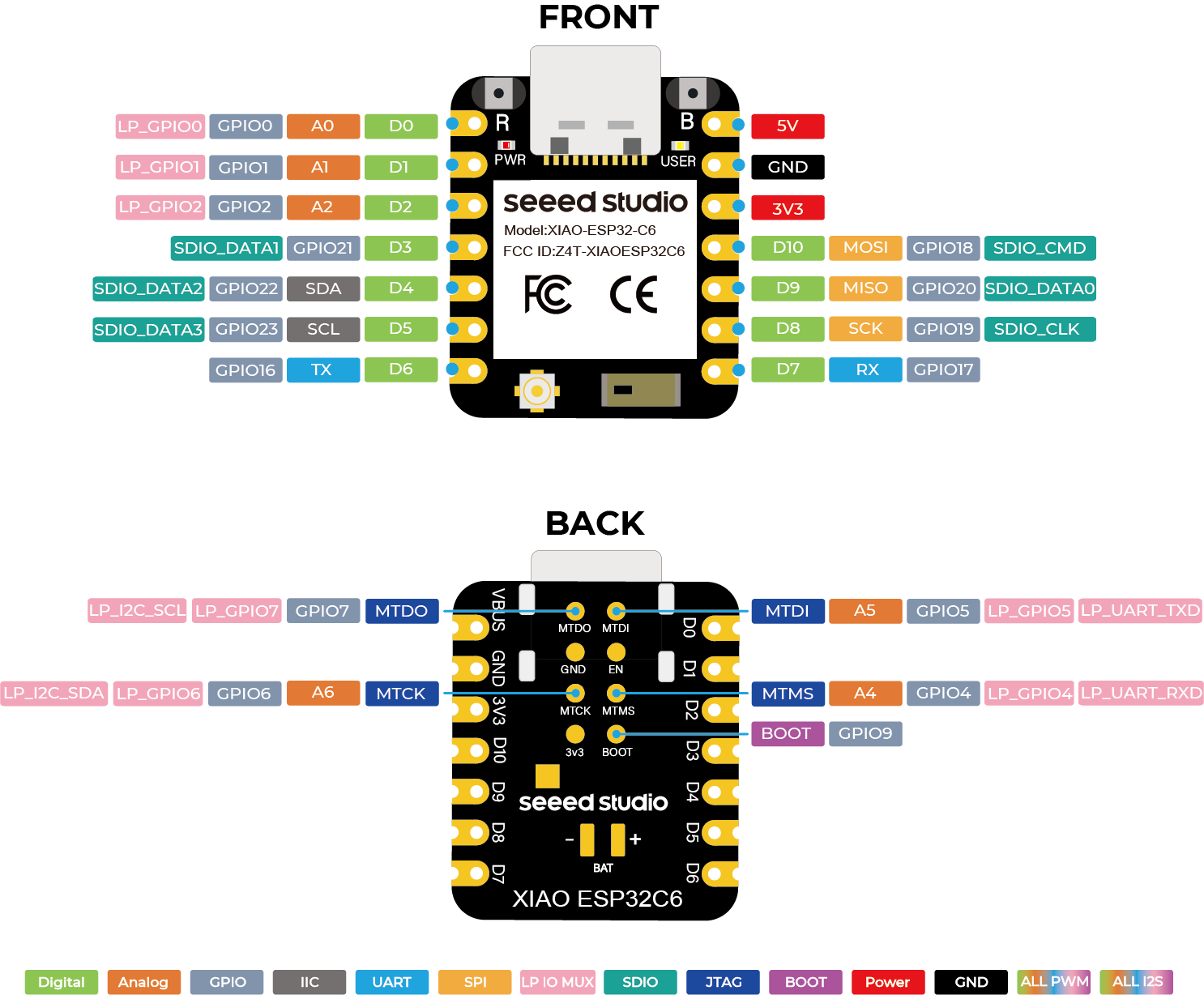
- More information please refer to hardware overview
- Seeed Studio XIAO ESP32C6 Schematic
Getting Started with CircuitPython on the XIAO ESP32C6
Network-WLAN
For boards without native USB (like ESP32-C6 or ESP32) you will need to use the REPL to connect to the Wi-Fi. Wi-Fi function is enabled when a file named settings.toml is added to the root folder of the CircuitPython file system.
Method 1: Create setting.toml file via REPL
Create settings.toml file via REPL:
f = open('settings.toml', 'w')
f.write('CIRCUITPY_WIFI_SSID = "wifissid"\n')
f.write('CIRCUITPY_WIFI_PASSWORD = "wifipassword"\n')
f.write('CIRCUITPY_WEB_API_PASSWORD = "webpassword"\n')
f.close()
-
Replace with the name of your local wifi network wifissid
-
Replace with your local wifi passwordwifi password
-
The other password, , is used when you access the board via a web browser. Set this to whatever you want webpassword
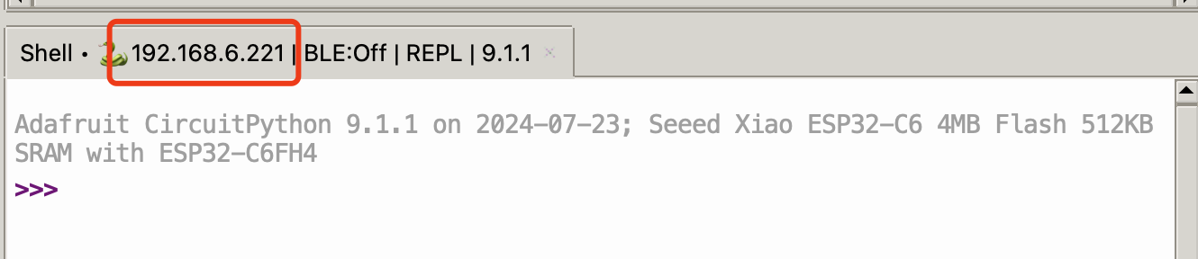
Once connected, you can press the Reset button to kick the firmware, then hit return a few times to get to the REPL prompt. Then reconnect device to Thonny, the IP address of your XIAO ESP32C6 shows up.
Method 2: Edit setting.toml file via Thonny Files
Open Thonny-->View-->Files, and wirte the wifi network, password and webpassword to setting.toml file. Remember to save it and press the Reset button to kick the firmware, and reopen Thonny.
Don't forget, ESP32 does not support 5 GHz networks, so use your 2.4 GHz SSID if you have two.
Delay and timing
The time module:
import time
dir(time)
time.sleep(1)           # sleep for 1 second
time.localtime()        # get local time
Pins and GPIO
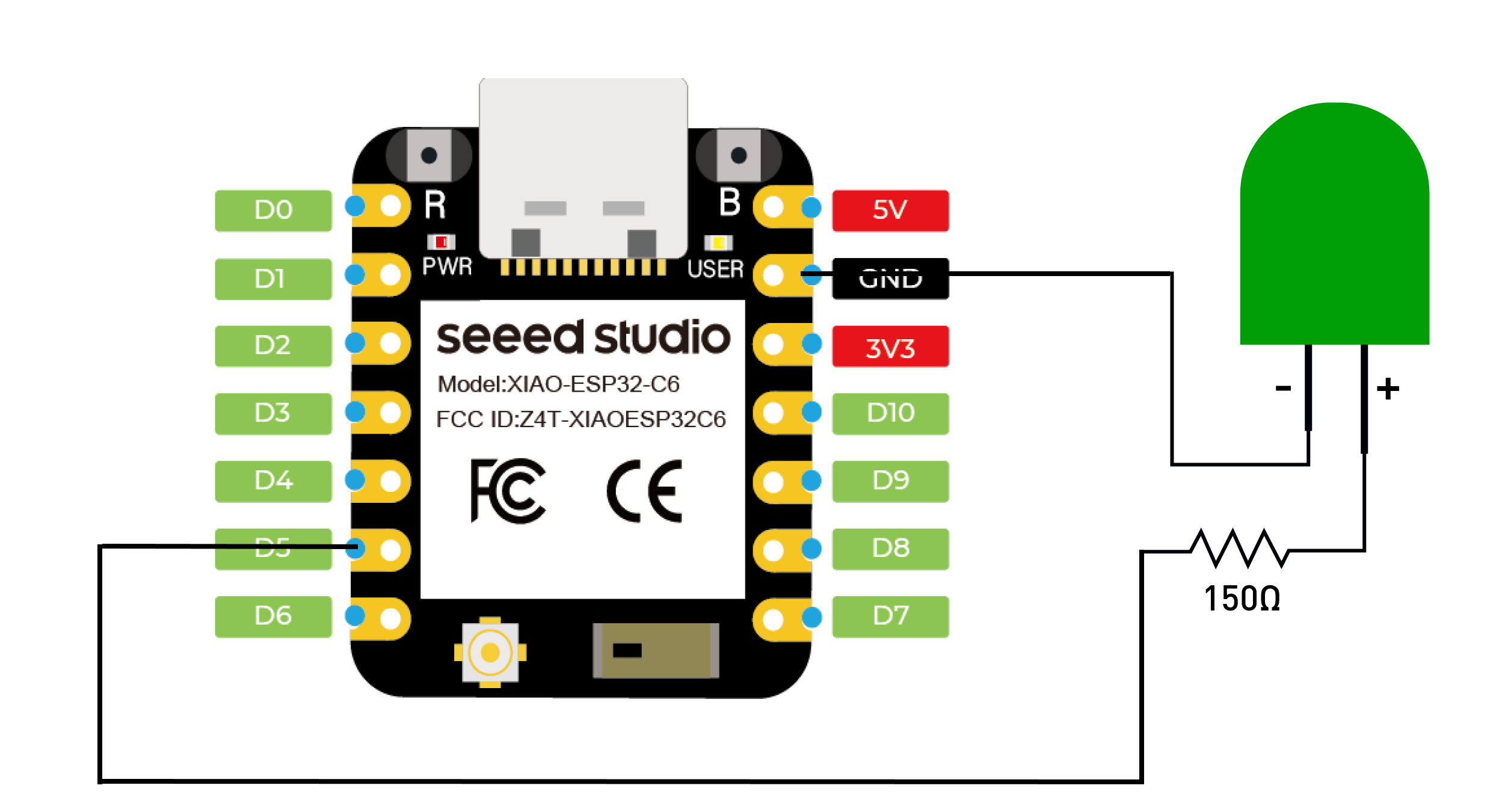
Can use module "board" and "microcontroller" to controller the gpio with the following code and connect a LED to D5:
# using board module
import board
import digitalio
import time
led = digitalio.DigitalInOut(board.D5)
led.direction = digitalio.Direction.OUTPUT
while True:
led.value = True # turn on LED
time.sleep(1)
led.value = False # turn off LED
time.sleep(1)
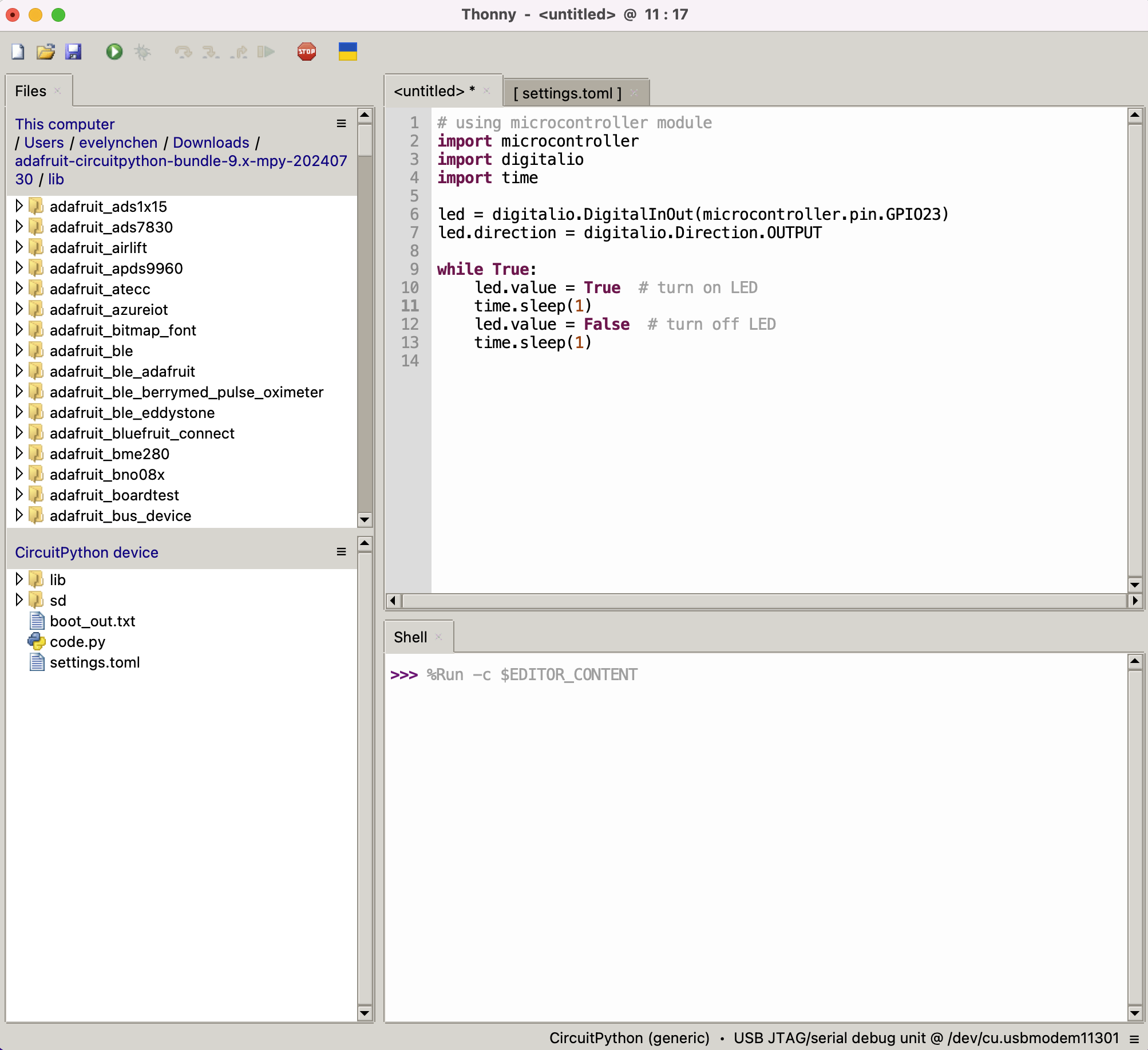
# using microcontroller module
import microcontroller
import digitalio
import time
led = digitalio.DigitalInOut(microcontroller.pin.GPIO23)
led.direction = digitalio.Direction.OUTPUT
while True:
led.value = True # turn on LED
time.sleep(1)
led.value = False # turn off LED
time.sleep(1)
UART(serial bus)
Using busio module:
import board
import busio

# initialise UART
uart = busio.UART(board.LP_UART_TXD, board.LP_UART_RXD, baudrate=9600)

# send data
uart.write(b"Hello UART\n")

# receive data
while True:
    if uart.in_waiting > 0:
        data = uart.read()
        print("Received:", data)
The XIAO ESP32C6 have one hardware UART. the pins listed below:
| UART | Pin | GPIO |
|---|---|---|
| LP_UART_TXD | A5 | GPIO5 |
| LP_UART_RXD | A4 | GPIO4 |
PWM(pulse width modulation)
Using pwmio module:
import board
import pwmio
from digitalio import DigitalInOut
import time

# initialise PWM
pwm = pwmio.PWMOut(board.D5, frequency=5000, duty_cycle=0)

# a dimming led
while True:
    for duty_cycle in range(0, 65535, 1000):
        pwm.duty_cycle = duty_cycle
        time.sleep(0.1)
ADC(analog to digital conversion)
Using the analogio module:
import board
import analogio
import time

# initialise ADC
adc = analogio.AnalogIn(board.A0)

while True:
    value = adc.value
    print("ADC Value:", value)
    time.sleep(1)
SPI
import board
import busio
import digitalio

# Initialize SPI
spi = busio.SPI(board.SCK, board.MOSI, board.MISO)
# Call try_lock (and later unlock) to ensure you are the only user of the SPI bus
spi.try_lock()

# Choose a chip select pin
cs = digitalio.DigitalInOut(board.D3)
cs.direction = digitalio.Direction.OUTPUT
cs.value = True

# Make sure chip select is active (low) before communicating
cs.value = False

# Send and receive data
data_out = bytearray([0x01, 0x02, 0x03])
data_in = bytearray(3)

try:
    # Write and read data
    spi.write_readinto(data_out, data_in)
    print("Received:", data_in)
finally:
    # Ensure chip select is inactive (high) after communication
    cs.value = True
The XIAO ESP32C6 have one hardware SPI. the pins listed below:
| SPI | Pin |
|---|---|
| SCK | D8 |
| MOSI | D10 |
| MISO | D9 |
I2C
import board
import busio

# Initialize I2C
i2c = busio.I2C(board.SCL, board.SDA, frequency=400000)
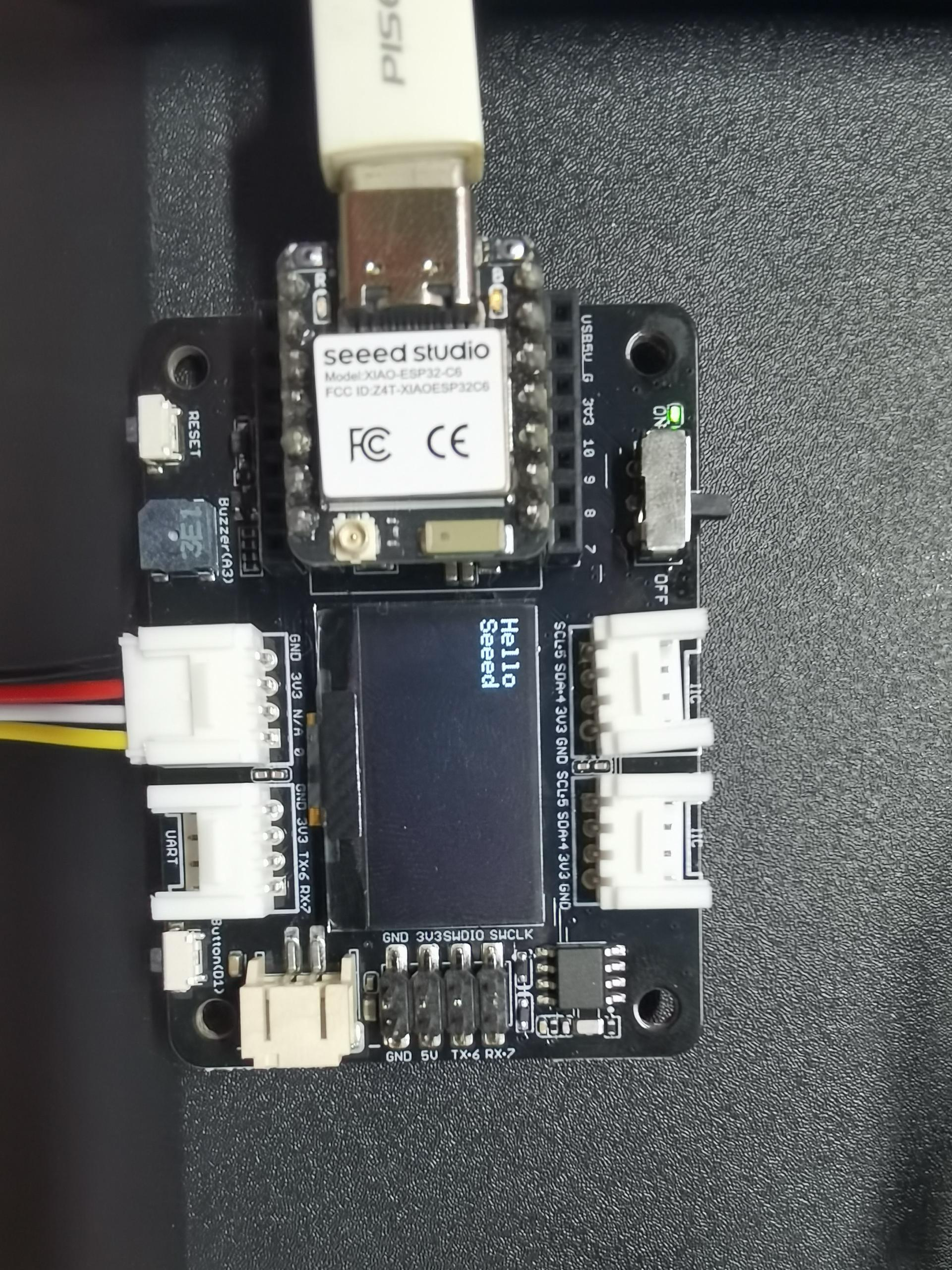
Expension Board Base for XIAO
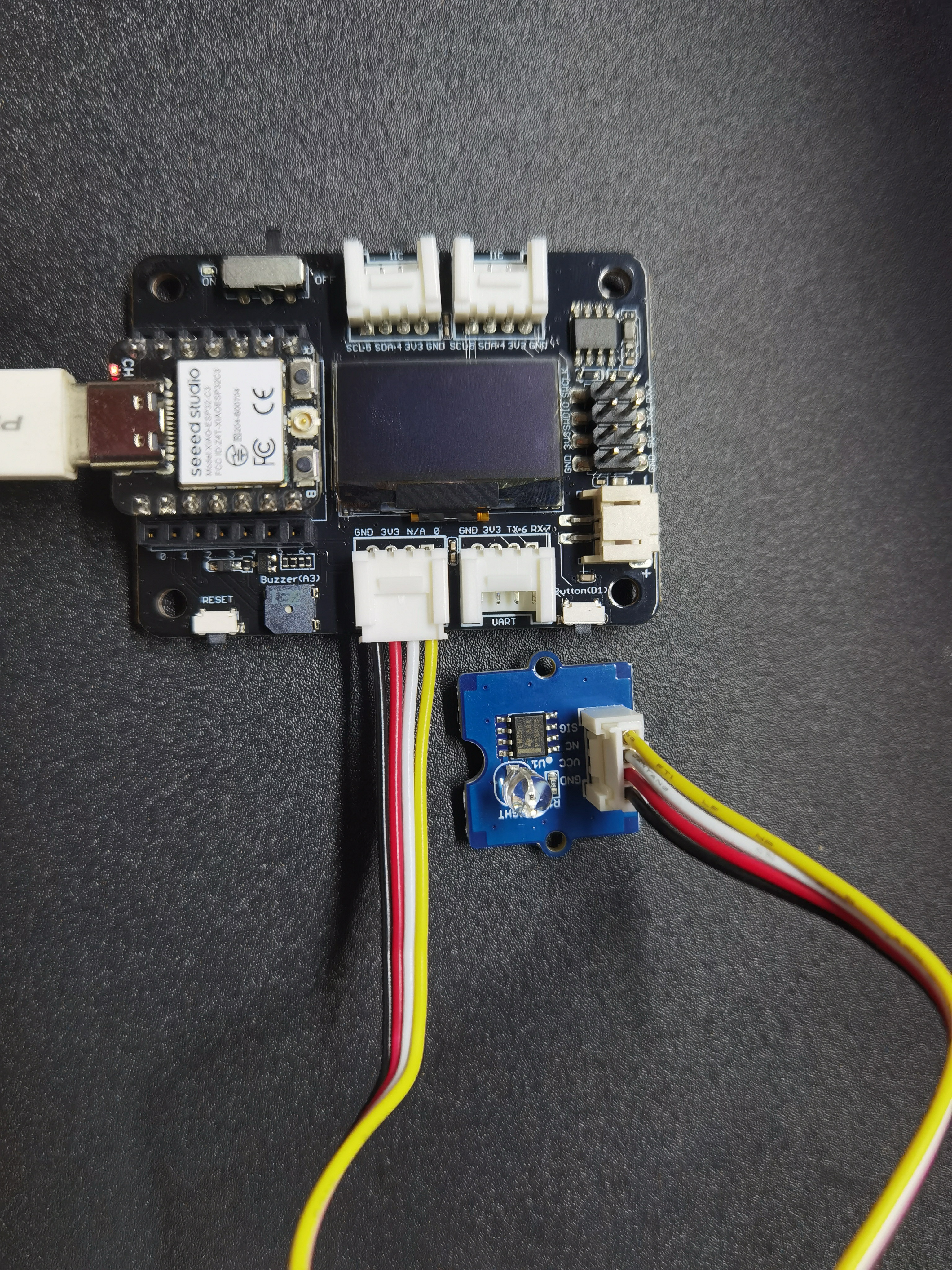
Prerequisites:
| XIAO ESP32C6 with soldered header | Expension Board Base for XIAO | Grove Light sensor |
|---|---|---|
 |  |  |
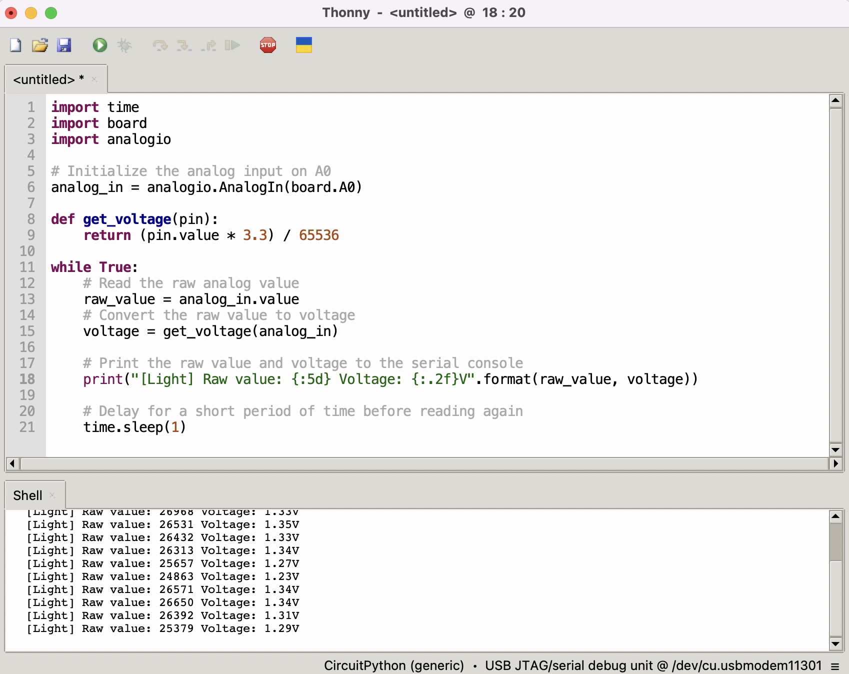
Read the light sensor data
import time
import board
import analogio

# Initialize the analog input on A0
analog_in = analogio.AnalogIn(board.A0)

def get_voltage(pin):
    return (pin.value * 3.3) / 65536

while True:
    # Read the raw analog value
    raw_value = analog_in.value
    # Convert the raw value to voltage
    voltage = get_voltage(analog_in)

    # Print the raw value and voltage to the serial console
    print("[Light] Raw value: {:5d} Voltage: {:.2f}V".format(raw_value, voltage))

    # Delay for a short period of time before reading again
    time.sleep(1)
Light up OLED screen
Download and Extract the Library Bundle:
- Go to the library and download the library bundle for CircuitPython. To install, download the appropriate bundle for your version of CircuitPython.
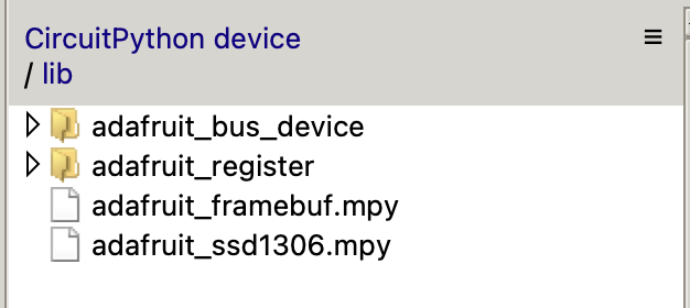
Copy Libraries to CIRCUITPY:
- Extract the library bundle ZIP file. You will find a folder named lib with various .mpy files.
- Open Thonny-->View-->Files, and then copy the necessary .mpy files and the lib folder to CircuitPython device/lib.
You'll need to manually install the necessary libraries from the bundle:
- adafruit_ssd1306
- adafruit_bus_device
- adafruit_register
- adafruit_framebuf.mpy
Copy fond5x8.bin to CIRCUITPY:
- Download font5x8.bin file from here.
- Open Thonny-->View-->Files, and then copy the font5x8.bin files to CircuitPython device.

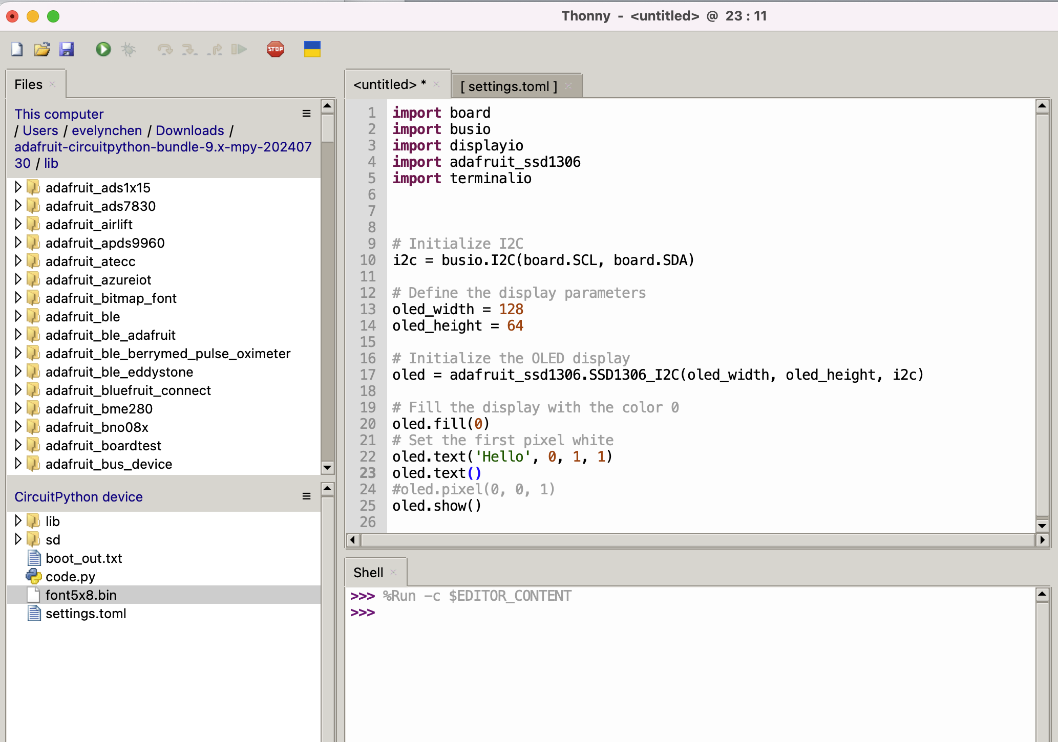
Create Your CircuitPython Code:
- Create a code.py file (or main.py) . This file should contain your CircuitPython code.
import board
import busio
import displayio
import adafruit_ssd1306
import terminalio

# Initialize I2C
i2c = busio.I2C(board.SCL, board.SDA)

# Define the display parameters
oled_width = 128
oled_height = 64

# Initialize the OLED display
oled = adafruit_ssd1306.SSD1306_I2C(oled_width, oled_height, i2c)

# Fill the display with the color 0
oled.fill(0)
# Set the first pixel white
oled.pixel(0, 0, 1)
oled.show()
"Uninstalling" CircuitPython
A lot of our boards can be used with multiple programming languages. For example, the Circuit Playground Express can be used with MakeCode, Code.org CS Discoveries, CircuitPython and Arduino. You may want to go back to Arduino or MakeCode. There is nothing to uninstall. CircuitPython is "just another program" that is loaded into your board. So you can simply load another program(Arduino or MakeCode) and it will overwrite CircuitPython.
Backup your Code
before replacing CircuitPython, don't forget to make a backup of the code you have on the CIRCUITPY drive. That means your code.py and any other files, the lib folder etc. You may lose these files when you remove CircuitPython, so backups are key! Just drag the files to a folder on your laptop or desktop computer like you would with any USB drive.
Moving to Arduino
If you want to use Arduino instead, you just use the Arduino IDE to load an Arduino program. Here's an example of uploading a simple "Blink" Arduino program, but you don't have to use this particular program. Start by plugging in your board, and double-clicking reset until you get the onboard LED(s).
Thank you for reading this article! Feel free to share your thoughts in the comments.
Resources
-
The firmware binary file for XIAO ESP32C6 with CircuitPython
Tech Support & Product Discussion
Thank you for choosing our products! We are here to provide you with different support to ensure that your experience with our products is as smooth as possible. We offer several communication channels to cater to different preferences and needs.