Grove - IMU 9DOF v2.0

Grove - IMU 9DOF v2.0 is an upgraded version of Grove - IMU 9DOF v1.0 and it is a high performance 9-axis motion tracking module, which is based on MPU-9250. The MPU-9250 is an integrated 9-axis motion tracking device designed for the low power, low cost, and high performance requirements of consumer electronics equipment including smartphones, tablets and wearable sensors. MPU-9250 features three 16-bit ADC for digitizing the gyroscope outputs and three 16-bit ADCs for digitizing the accelerometer outputs and three 16-bit ADCs for digitizing the magnetometer outputs.

Specifications
- I2C/SPI interface
- Auxiliary I2C
- Low Power Consumption
- 400kHz Fast Mode I2C for communicating with all registers
- Digital-output 3-Axis angular rate sensors (gyroscopes) with a user-programmable full-scale range of ±250, ±500, ±1000, and ±2000°/sec
- Digital-output 3-Axis accelerometer with a programmable full scale range of ±2g, ±4g, ±8g and ±16g
- Digital-output 3-Axis accelerometer with a full scale measurement range is ±4800μT
- I2C Address: 0x68
If you want to use multiplue I2C devices, please refer to [Software I2C](https://wiki.seeedstudio.com/Arduino_Software_I2C_user_guide/).
More details about Grove modules please refer to [Grove System](https://wiki.seeedstudio.com/Grove_System/)
Platforms Supported
| Arduino | Raspberry Pi |
|---|---|
|
|
The platforms mentioned above as supported is/are an indication of the module's software or theoritical compatibility. We only provide software library or code examples for Arduino platform in most cases. It is not possible to provide software library / demo code for all possible MCU platforms. Hence, users have to write their own software library.
Hardware Overview


① - Grove interface,connect to I2C
② - I2C or SPI select pad(default is I2C), if want to use SPI, disconnect this pad
③ - Address select pad, default connected b and c address is 0x68, if connect b and a address is 0x69, if want to use SPI, disconnect this pad to either side.
④ - SPI Interface
⑤ - Auxiliary I2C master serial data
⑥ - Auxiliary I2C master serial clock
⑦ - Interrupt digital output
Getting started
Play with Arduino
Hardware
- Step 1. Prepare the below stuffs:
| Seeeduino V4.2 | Base Shield | Grove-IMU_9DOF_v2.0 |
|---|---|---|
|
|
|
| Get One Now | Get One Now | Get One Now |


- Step 2. Connect Grove-IMU_9DOF_v2.0 to port I2C of Grove-Base Shield.
- Step 3. Plug Grove - Base Shield into Seeeduino.
- Step 4. Connect Seeeduino to PC via a USB cable.
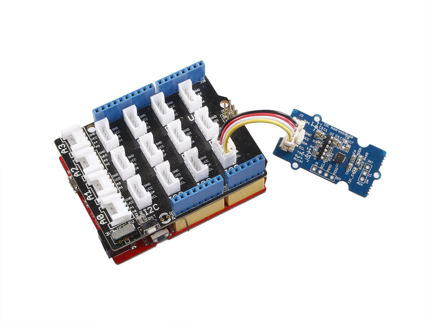
If we don't have Grove Base Shield, We also can directly connect this module to Seeeduino as below.
| Seeeduino_v4 | Grove-IMU_9DOF_v2.0 |
|---|---|
| 5V | VCC |
| GND | GND |
| SDA | SDA |
| SCL | SCL |
Software
Step 1. Download the library. from Github.
Step 2. Refer How to install library to install library for Arduino.
Step 3. Create a new Arduino sketch and paste the codes below to it or open the code directly by the path:File -> Example ->IMU_9DOF_Demo_Compass_Calibrated->IMU_9DOF_Demo_Compass_Calibrated.
Here is the main part of the code
void setup() {
  // join I2C bus (I2Cdev library doesn't do this automatically)
  Wire.begin();

  // initialize serial communication
  // (38400 chosen because it works as well at 8MHz as it does at 16MHz, but
  // it's really up to you depending on your project)
  Serial.begin(38400);

  // initialize device
  Serial.println("Initializing I2C devices...");
  accelgyro.initialize();

  // verify connection
    Serial.println("Testing device connections...");
    Serial.println(accelgyro.testConnection() ? "MPU9250 connection successful" : "MPU9250 connection failed");
    delay(1000);
    Serial.println("     ");

 //Mxyz_init_calibrated ();
}

void loop()
{
    getAccel_Data();
    getGyro_Data();
    getCompassDate_calibrated(); // compass data has been calibrated here
    getHeading();               //before we use this function we should run 'getCompassDate_calibrated()' frist, so that we can get calibrated data ,then we can get correct angle .
    getTiltHeading();

    Serial.println("calibration parameter: ");
    Serial.print(mx_centre);
    Serial.print("         ");
    Serial.print(my_centre);
    Serial.print("         ");
    Serial.println(mz_centre);
    Serial.println("     ");


    Serial.println("Acceleration(g) of X,Y,Z:");
    Serial.print(Axyz[0]);
    Serial.print(",");
    Serial.print(Axyz[1]);
    Serial.print(",");
    Serial.println(Axyz[2]);
    Serial.println("Gyro(degress/s) of X,Y,Z:");
    Serial.print(Gxyz[0]);
    Serial.print(",");
    Serial.print(Gxyz[1]);
    Serial.print(",");
    Serial.println(Gxyz[2]);
    Serial.println("Compass Value of X,Y,Z:");
    Serial.print(Mxyz[0]);
    Serial.print(",");
    Serial.print(Mxyz[1]);
    Serial.print(",");
    Serial.println(Mxyz[2]);
    Serial.println("The clockwise angle between the magnetic north and X-Axis:");
    Serial.print(heading);
    Serial.println(" ");
    Serial.println("The clockwise angle between the magnetic north and the projection of the positive X-Axis in the horizontal plane:");
    Serial.println(tiltheading);
    Serial.println("   ");
    Serial.println("   ");
    Serial.println("   ");
    delay(300);
}

Step 4. Upload the code and after that, you can see :
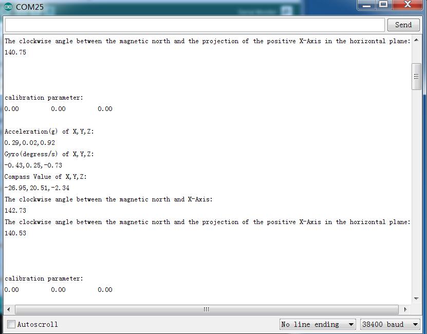
In static state,the z-Axis output value is about 0.98g,so you can refer to this to test if your sensor can work normally.
References
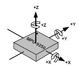
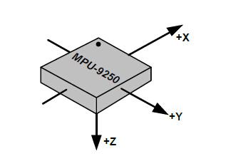
Orientation of Axes
The diagram below shows the orientation of the axes of sensitivity and the polarity of rotation.Note the pin 1 identifier (•) in the figure.
- Orientation of Axes of Sensitivity and Polarity of Rotation for Accelerometer and Gyroscope
- Orientation of Axes of Sensitivity for Compass
Schematic Online Viewer
Resources
- [Eagle&PDF] Grove - IMU 9DOF v2.0 Eagle File
- [Library] Grove - IMU 9DOF v2.0 library
- [PDF] MPU-9250 datashet
- [PDF] MPU-9250 Register Map
Projects
Speed testing the MPU9150's functions using a LinkIt ONE : I set up this project with the sole intention of determining the cost in milliseconds of the MPU9150's standard functions.
Tech Support & Product Discussion
Thank you for choosing our products! We are here to provide you with different support to ensure that your experience with our products is as smooth as possible. We offer several communication channels to cater to different preferences and needs.