XIAO ESP32S3(Sense) With FreeRTOS
This wiki covers FreeRTOS support for the Seeed Studio XIAO ESP32S3. With the assistance of this guide you will be able to utilize the feature set available to the board.
What is FreeRTOS

FreeRTOS is a collection of C libraries comprised of a real-time kernel and a set of modular libraries that implement complementary functionality. The FreeRTOS kernel is a real-time kernel (or real-time scheduler) that enables applications built on FreeRTOS to meet their hard real-time requirements. It enables applications to be organized as a collection of independent threads of execution.
Reference : Mastering the FreeRTOS Real Time Kernel
FreeRTOS ports
FreeRTOS is an open source RTOS (real-time operating system) kernel that is integrated into ESP-IDF as a component. Thus, all ESP-IDF applications and many ESP-IDF components are written based on FreeRTOS. The FreeRTOS kernel is ported to all architectures (i.e., Xtensa and RISC-V) available of ESP chips.
We will be using the ESP IDF port of the FreeRTOS.
Hardware Preparation
I am using Seed Studio XIAO ESP32S3 Sense and the onboard camera, microphone and sd-card reader along with the Wifi functionality of the ESP32S3.
| Seeed Studio XIAO ESP32S3(Sense) |
|---|
 |
Additional Components
- Grove - Expansion Board - I2C Display RTC & Button
- Air Quality Sensor v1.3
- Grove - Temperature, Humidity, Pressure and Gas Sensor for Arduino - BME680
- Acrylic Case for Seeed Studio XIAO Expansion board
Software Preparation
I am using Visual Studio Code (Windows) with ESP-IDF.
- VSCode install
- ESP-IDF installation guide
- Git Repository
| VS Code | ESP-IDF for VSCode |
|---|---|
Getting Started
Setting up ESP-IDF
After setting up the Visual Studio Extension, open the terminal and paste the following command to access the ESP-IDF Command Line Tools from the normal terminal environment(outside of VScode).
The normal installation of ESP-IDF extension of VS-Code will take care of 90% of use cases do the following steps only if you need ESP Command line tools outside of the environment.
PowerShell (Windows)
.$HOME\esp\v5.3\esp-idf\export.ps1
".$HOME\esp\v5.3\esp-idf" may differ from user to user.This the default installation path.
Replace it wil the installation path on your device.
To avoid repeated setup boot up PowerShell in administrator mode and type the following command
notepad $PSHOME\Profile.ps1
A Notepad instance will open up. Paste the export shell command in the note-pad and save it. open an instance of powershell and it should have close to the following output.
Done! You can now compile ESP-IDF projects.
If everything is done properly, the following command :
idf.py
should show the following output :
Usage: idf.py [OPTIONS] COMMAND1 [ARGS]... [COMMAND2 [ARGS]...]...

  ESP-IDF CLI build management tool. For commands that are not known to idf.py an attempt to execute it as a build
  system target will be made. Selected target: None
Board Configuration for XIAO ESP32S3
After setting up ESP-IDF, you need to configure your project specifically for the XIAO ESP32S3 board to take advantage of its hardware features including 8MB Flash and 8MB Octal PSRAM.
Set Target Device
In your ESP-IDF project directory, set the target to ESP32-S3:
idf.py set-target esp32s3
Enable Full Build Options
In your project's root CMakeLists.txt, ensure MINIMAL_BUILD is set to OFF:
idf_build_set_property(MINIMAL_BUILD OFF)
This enables all configuration options in menuconfig.
Configure Flash and PSRAM
Open the configuration menu:
idf.py menuconfig
Flash Size Configuration:
- Navigate to: Serial flasher config → Flash size
- Set to: 8 MB
PSRAM Configuration:
- Navigate to: Component config → ESP PSRAM
- Enable: Support for external, SPI-connected RAM
- Set SPI RAM mode to: Octal Mode PSRAM
- Set SPI RAM clock to: 80MHz
The XIAO ESP32S3 uses Octal PSRAM, not Quad mode. Selecting the correct mode is essential for the 8MB PSRAM to function properly.
Update Main Component Dependencies
In /main/CMakeLists.txt, ensure PSRAM and SPI flash components are included:
idf_component_register(
    SRCS "main.c"
    INCLUDE_DIRS "."
    PRIV_REQUIRES esp_psram spi_flash
)
Create Board Pin Configuration Component
Create a reusable component for XIAO pin definitions to make your code more readable and portable:
mkdir -p ./components/board_config/include/
Create ./components/board_config/include/xiao_pins.h:
// xiao_pins.h
#pragma once

#ifdef __cplusplus
extern "C" {
#endif

// Analog / Digital Pins
#define XIAO_D0     1
#define XIAO_D1     2
#define XIAO_D2     3
#define XIAO_D3     4
#define XIAO_D4     5
#define XIAO_D5     6
#define XIAO_D6     43
#define XIAO_D7     44
#define XIAO_D8     7
#define XIAO_D9     8
#define XIAO_D10    9

// Onboard User LED (Active Low)
#define XIAO_LED    21

// I2C Pins (Default)
#define XIAO_SDA    5   // Same as D4
#define XIAO_SCL    6   // Same as D5

// SPI Pins (Default)
#define XIAO_MISO   9   // Same as D10
#define XIAO_MOSI   10
#define XIAO_SCK    8   // Same as D9
#define XIAO_SS     7   // Same as D8

#ifdef __cplusplus
}
#endif
Create ./components/board_config/CMakeLists.txt:
idf_component_register(INCLUDE_DIRS "include")
These pin definitions match the silkscreen labels on the XIAO ESP32S3 board, making your code more readable. For example, use XIAO_LED instead of hard-coding GPIO 21.
Use Pin Definitions in Your Code
In your main application or any component, include the header:
#include "xiao_pins.h"

void app_main(void) {
    // Example: Configure LED pin
    gpio_set_direction(XIAO_LED, GPIO_MODE_OUTPUT);
    gpio_set_level(XIAO_LED, 0);  // Turn on (active low)
}
Pin Mapping Reference
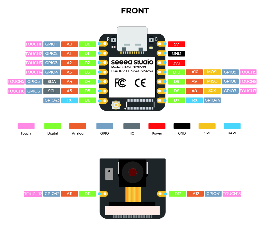
| Label | GPIO | Alt Function |
|---|---|---|
| D0 | 1 | ADC1_CH0 |
| D1 | 2 | ADC1_CH1 |
| D2 | 3 | ADC1_CH2 |
| D3 | 4 | ADC1_CH3 |
| D4 | 5 | ADC1_CH4, SDA |
| D5 | 6 | ADC1_CH5, SCL |
| D6 | 43 | TX |
| D7 | 44 | RX |
| D8 | 7 | ADC1_CH6, SS |
| D9 | 8 | ADC1_CH7, SCK |
| D10 | 9 | ADC1_CH8, MISO |
- GPIO 19 and 20 are used for USB D-/D+ and should not be reconfigured
- The onboard LED on GPIO 21 is active LOW (set to 0 to turn on)
- All pins D0-D10 support analog input via ADC1
Building and Flashing
Build your project:
idf.py build
Flash to the XIAO ESP32-S3:
idf.py -p /dev/ttyACM0 flash monitor
Replace /dev/ttyACM0 with your actual serial port (on Windows, typically COM3, COM4, etc.).
Troubleshooting Board Configuration
PSRAM Not Detected:
- Verify Octal mode is selected (not Quad)
- Check that flash size is set to 8MB
- Ensure ESP-IDF version is 4.4 or later
Upload Fails:
- Press and hold the BOOT button while connecting USB
- Try reducing upload speed:
idf.py -p PORT -b 115200 flash
Pin Conflicts:
- Avoid using GPIO pins 19 and 20 (USB D- and D+)
- XIAO_LED (GPIO 21) is shared with the onboard LED
What are Task?
Tasks are small functions/ jobs that the the processor is requested to perform with a set of settings. Tasks can range from small functions to infinite looping functions.
Tasks are the fundamental units of execution in an ESP-IDF application. They are essentially functions that run concurrently with other tasks. This allows for efficient multitasking and responsiveness.
What are task properties?
Due to the vastness of this topic, i will be only covering a few of the properties we will be using for this guide.
- TaskFunction: This is the function that contains the actual logic of the task. It's the entry point for the task's execution.
- StackSize: This specifies the amount of memory allocated for the task's stack. The stack is used to store local variables, function return addresses, and temporary data.
- TaskPriority: This determines the relative importance of the task compared to other tasks. Higher-priority tasks have a greater chance of being executed before lower-priority ones.
- TaskParameters: These are optional arguments that can be passed to the task function when it's created. They can be used to provide additional context or configuration to the task.
- CoreAffinity: This specifies which CPU core the task should be assigned to. In systems with multiple cores, this can be used to optimize performance or balance the workload.
Creating a task
To create a task in FreeRTOS, the xTaskCreate function is used. This function takes several parameters, including the task function, task name, stack size, parameters, priority, and a handle to the created task.
TaskHandle_t task;
xTaskCreate(
        taskFunction,             /* Function that implements the task. */
        "taskName",               /* Text name for the task. */
        configMINIMAL_STACK_SIZE, /* Stack size in words, or bytes. */
        NULL,                     /* Parameter passed into the task. */
        tskIDLE_PRIORITY,         /* Priority at which the task is created. */
        &task                     /* Used to pass out the created task's handle. */
        );
Creating a task pinned to a core
To create a task and pin it to a specific core (only if the chip in use is dual core), the xTaskCreatePinnedToCore function is used. This function is similar to xTaskCreate but includes an additional parameter for specifying the core.
TaskHandle_t task;
xTaskCreatePinnedToCore(
        taskFunction,             /* Function that implements the task. */
        "taskName",               /* Text name for the task. */
        configMINIMAL_STACK_SIZE, /* Stack size in words, or bytes. */
        NULL,                     /* Parameter passed into the task. */
        tskIDLE_PRIORITY,         /* Priority at which the task is created. */
        &task,                    /* Used to pass out the created task's handle. */
        0);                       /* Core ID */
Task function call
The task function is the actual code that will be executed by the task.
void taskFunction(void * pvParameters) {
  /*
  Function definition goes here
  */
}
Visualization of tasks
I am creating four simple task to visualize how the FreeRTOS works.
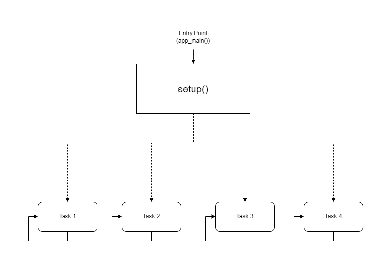
Visual Representation
CPU0
-----
taskFunction1 (1000ms delay)

CPU1
-----
taskFunction2 (500ms delay)
taskFunction3 (500ms delay)
taskFunction4 (500ms delay)
Code
#include <stdio.h>
#include "freertos/FreeRTOS.h"
#include "freertos/task.h"
#include "sdkconfig.h"
#include "esp_log.h"

TaskHandle_t task1,task2,task3,task4;

void taskFunction1(void * pvParameters) {
    while (true) {
        ESP_LOGI("Task1", "Hello from task 1");
        vTaskDelay(pdMS_TO_TICKS(1000)); // Add a delay to avoid overwhelming the output
    }
}

void taskFunction2(void * pvParameters) {
    while (true) {
        ESP_LOGI("Task2", "Hello from task 2");
        vTaskDelay(pdMS_TO_TICKS(500)); // Add a delay to avoid overwhelming the output
    }
}

void taskFunction3(void * pvParameters) {
    while (true) {
        ESP_LOGI("Task3", "Hello from task 3");
        vTaskDelay(pdMS_TO_TICKS(500)); // Add a delay to avoid overwhelming the output
    }
}

void taskFunction4(void * pvParameters) {
    while (true) {
        ESP_LOGI("Task4", "Hello from task 4");
        vTaskDelay(pdMS_TO_TICKS(500)); // Add a delay to avoid overwhelming the output
    }
}

void app_main(void) {
    xTaskCreatePinnedToCore(
        taskFunction1, /* Function that implements the task. */
        "task_1",        /* Text name for the task. */
        configMINIMAL_STACK_SIZE, /* Stack size in words, not bytes. */
        NULL,            /* Parameter passed into the task. */
        tskIDLE_PRIORITY, /* Priority at which the task is created. */
        &task1,         /* Used to pass out the created task's handle. */
        0);              /* Core ID */

    xTaskCreatePinnedToCore(
        taskFunction2, /* Function that implements the task. */
        "task_2",        /* Text name for the task. */
        configMINIMAL_STACK_SIZE, /* Stack size in words, not bytes. */
        NULL,            /* Parameter passed into the task. */
        tskIDLE_PRIORITY, /* Priority at which the task is created. */
        &task2,         /* Used to pass out the created task's handle. */
        1);              /* Core ID */

    xTaskCreatePinnedToCore(
        taskFunction3, /* Function that implements the task. */
        "task_3",        /* Text name for the task. */
        configMINIMAL_STACK_SIZE, /* Stack size in words, not bytes. */
        NULL,            /* Parameter passed into the task. */
        tskIDLE_PRIORITY, /* Priority at which the task is created. */
        &task3,         /* Used to pass out the created task's handle. */
        1);              /* Core ID */

    xTaskCreatePinnedToCore(
        taskFunction4, /* Function that implements the task. */
        "task_4",        /* Text name for the task. */
        configMINIMAL_STACK_SIZE, /* Stack size in words, not bytes. */
        NULL,            /* Parameter passed into the task. */
        tskIDLE_PRIORITY, /* Priority at which the task is created. */
        &task4,         /* Used to pass out the created task's handle. */
        1);              /* Core ID */
}
configMINIMAL_STACK_SIZE can be changed in sdkconfig.
- Four Tasks: The code defines four tasks: taskFunction1, taskFunction2, taskFunction3, and taskFunction4.
- Task Priorities: All tasks are created with the tskIDLE_PRIORITY. This means they have the same priority.
- Task Pinning: taskFunction1 is pinned to CPU0, while the other three tasks are pinned to CPU1.
- Task Delays: taskFunction1 has a delay of 1000ms, while the other three have a delay of 500ms.
Creating the CPU0 and CPU1 Task Schedule
I have create a basic task schedule for CPU0 and CPU1.
CPU0 Task Schedule
Task: taskFunction1
Priority: Idle (lowest)
Delay: 1000ms
Core: 0
CPU1 Task Schedule
Tasks: taskFunction2, taskFunction3, taskFunction4
Priorities: All Idle (same priority)
Delays: 500ms for all tasks
Core: 1
This is a simplified schedule. Actual task scheduling in a real-time system would involve more complex factors like task priorities, deadlines, and resource constraints.
Output
I (11412) Task1: Hello from task 1
I (11522) Task3: Hello from task 3
I (11522) Task2: Hello from task 2
I (11532) Task4: Hello from task 4
I (12032) Task3: Hello from task 3
I (12032) Task2: Hello from task 2
I (12042) Task4: Hello from task 4
I (12422) Task1: Hello from task 1
I (12542) Task3: Hello from task 3
I (12542) Task2: Hello from task 2
I (12552) Task4: Hello from task 4
I (13052) Task3: Hello from task 3
I (13052) Task2: Hello from task 2
I (13062) Task4: Hello from task 4
I (13432) Task1: Hello from task 1
I (13562) Task3: Hello from task 3
I (13562) Task2: Hello from task 2
I (13572) Task4: Hello from task 4
I (14072) Task3: Hello from task 3
I (14072) Task2: Hello from task 2
I (14082) Task4: Hello from task 4
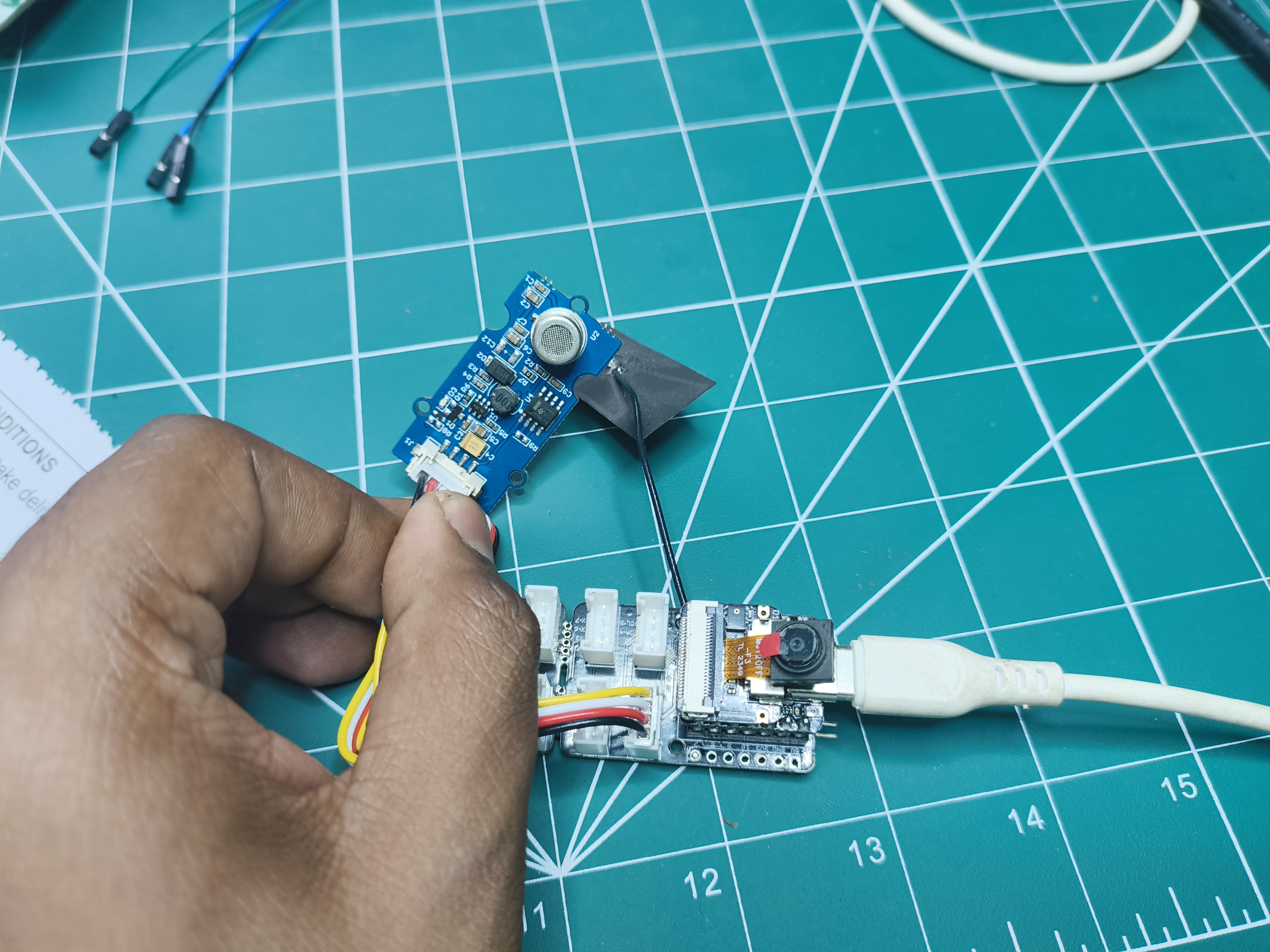
Sensor polling using FreeRTOS
For this I am using an analog sensor Air Quality Sensor v1.3 along with ESP_IDF_v5.3.
Hardware Setup
Attach the Xiao-S3 to the Grove - Expansion Board and connect the Air Quality Sensor v1.3 to the analog connector.
Software Setup
After pulling the git repository, open the folder in VSCode. Go to View->Command Palette->ESP-IDF: Add vscode Configuration Folder. From the bottom panel select the correct COM port, chip (ESP-S3) and build,flash and monitor.
Code Overview
This code is designed to collect air quality data from a sensor, process the raw data to determine the air quality level, and periodically print the results to the console.
Key Components
- Sensor Initialization:
air_quality_sensor_t air_quality_sensor;

void sensor_setup()
{
    air_quality_sensor._io_num = ADC_CHANNEL_0;
    air_quality_sensor._adc_num = ADC_UNIT_1;
    printf("Starting Air Quality Sensor...\n");
    if(!initialize_air_quality_sensor(&air_quality_sensor))
    {
        printf("Sensor ready.\n");
    }
    else{
        printf("Sensor ERROR!\n");
    }
}
-
sensor_setup() function configures the sensor's I/O pins and ADC unit.
-
It attempts to initialize the sensor using initialize_air_quality_sensor().
-
If initialization is successful, the sensor is ready for data collection.
-
Data Collection Task:
void poll_read_air_quality_sensor(void *pvParameters)
{
    for (;;)
    {
        air_quality_sensor_slope(&air_quality_sensor);
        vTaskDelay(500 / portTICK_PERIOD_MS);
    }
}
-
poll_read_air_quality_sensor() task is created to continuously read raw data from the sensor.
-
It calls air_quality_sensor_slope() to process the raw data and calculate the slope, which is an indicator of air quality.
-
The task delays for 500 milliseconds before reading the next data point.
-
Data Printing Task:
void print_read_air_quality_sensor(void *pvParameters)
{
    for (;;)
    {
        char buf[40];
        air_quality_error_to_message(air_quality_sensor._air_quality,buf);
        printf("Time : %lu\tSlope : %d\tRaw Value : %d\n%s\n", (uint32_t)esp_timer_get_time() / 1000, air_quality_sensor._air_quality, air_quality_sensor._sensor_raw_value,buf);
        vTaskDelay(1000 / portTICK_PERIOD_MS);
    }
}
- print_read_air_quality_sensor() task is created to periodically print the collected data and calculated air quality.
- It retrieves the current time, slope, raw value, and air quality message using air_quality_error_to_message().
- The task prints the data to the console in a formatted manner.
- The task delays for 1000 milliseconds before printing the next data point.
void app_main(void)
{
    sensor_setup();
    xTaskCreatePinnedToCore(
        poll_read_air_quality_sensor,   /* Function that implements the task. */
        "poll_read_air_quality_sensor", /* Text name for the task. */
        configMINIMAL_STACK_SIZE * 2,   /* Stack size in words, not bytes. */
        NULL,                           /* Parameter passed into the task. */
        tskIDLE_PRIORITY,               /* Priority at which the task is created. */
        NULL,                           /* Used to pass out the created task's handle. */
        0);                             /* Core ID */

    xTaskCreatePinnedToCore(
        print_read_air_quality_sensor,   /* Function that implements the task. */
        "print_read_air_quality_sensor", /* Text name for the task. */
        configMINIMAL_STACK_SIZE * 2,    /* Stack size in words, not bytes. */
        NULL,                            /* Parameter passed into the task. */
        tskIDLE_PRIORITY + 1,            /* Priority at which the task is created. */
        NULL,                            /* Used to pass out the created task's handle. */
        0);                              /* Core ID */
}
Output
Time : 37207    Slope : 3       Raw Value : 273
Fresh air.
Time : 38217    Slope : 3       Raw Value : 269
Fresh air.
Time : 39227    Slope : 3       Raw Value : 274
Fresh air.
Time : 40237    Slope : 3       Raw Value : 251
Fresh air.
Time : 41247    Slope : 3       Raw Value : 276
Fresh air.
Time : 42257    Slope : 3       Raw Value : 250
Fresh air.
Time : 43267    Slope : 3       Raw Value : 236
Fresh air.
Time : 44277    Slope : 3       Raw Value : 253
Fresh air.
Time : 45287    Slope : 3       Raw Value : 245
Fresh air.
Time : 46297    Slope : 3       Raw Value : 249
Fresh air.
Time : 47307    Slope : 3       Raw Value : 244
Fresh air.
Time : 48317    Slope : 3       Raw Value : 235
Fresh air.
Time : 49327    Slope : 3       Raw Value : 239
Fresh air.
Time : 50337    Slope : 3       Raw Value : 233
Fresh air.
Time : 51347    Slope : 3       Raw Value : 235
Fresh air.
Camera and SdCard usage in FreeRTOS
For this I am using the onBoard Camera and SdCard along with ESP_IDF_v5.3.
Hardware Setup
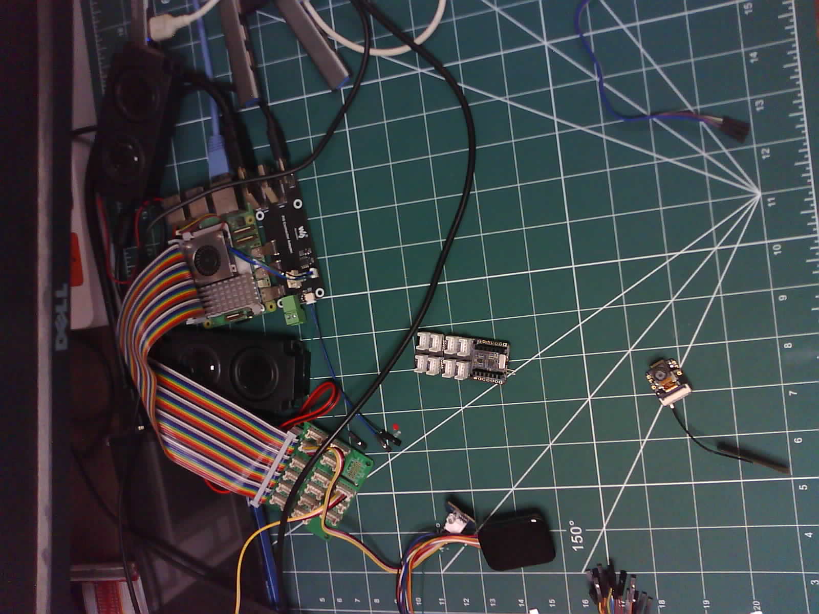
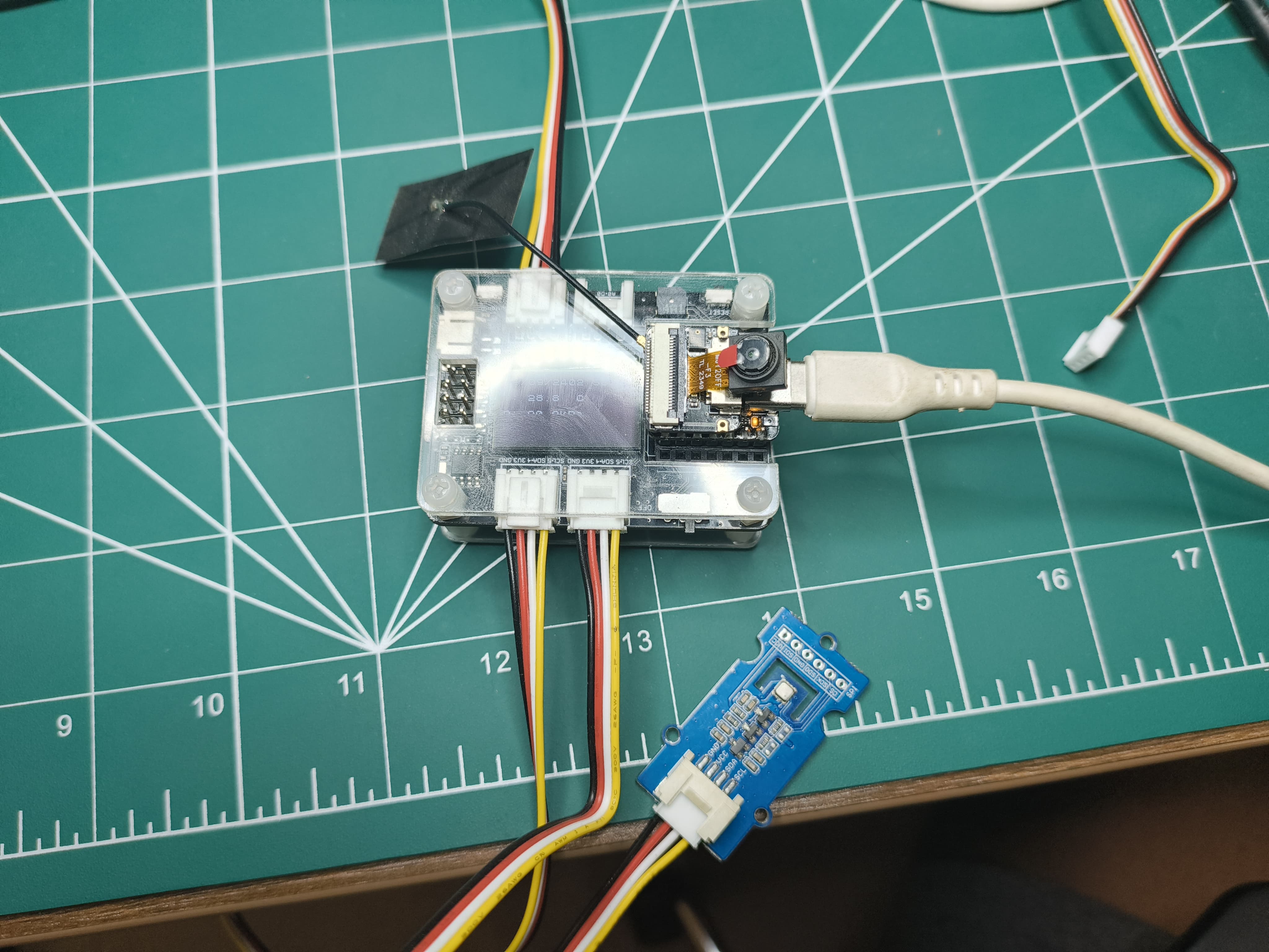
Follow the microSD card guide and camera guide to attach the camera and microSD card extension board to the
- Format microSD card (supported up to 32Gb)
- Attach the microSD card to the extension board
The setup would look something like this :
| Front | Back |
|---|---|
 |  |
Software Setup
After pulling the git repository, open the folder in VSCode. Go to View->Command Palette->ESP-IDF: Add vscode Configuration Folder. From the bottom panel select the correct COM port, chip (ESP-S3) and build,flash and monitor.
If you are using the OV3660 model, you need to set it up in the IDF to be able to drive it. input "idf.py menuconfig" in your terminal
| Step 1 | Step 2 | Step 3 |
|---|---|---|
 |  |  |
Camera Component
- Camera Configuration:
- Defines the GPIO pins used for various camera functions (PWDN, RESET, XCLK, SIOD, SIOC, Y9-Y2, VSYNC, HREF, PCLK, LED).
- Sets default values for camera parameters (e.g., clock frequency, frame buffer location, pixel format, frame size, JPEG quality, frame buffer count, grab mode).
#ifndef CAMERA_CONFIG_H
#define CAMERA_CONFIG_H

#define PWDN_GPIO_NUM     -1
#define RESET_GPIO_NUM    -1
#define XCLK_GPIO_NUM     10
#define SIOD_GPIO_NUM     40
#define SIOC_GPIO_NUM     39

#define Y9_GPIO_NUM       48
#define Y8_GPIO_NUM       11
#define Y7_GPIO_NUM       12
#define Y6_GPIO_NUM       14
#define Y5_GPIO_NUM       16
#define Y4_GPIO_NUM       18
#define Y3_GPIO_NUM       17
#define Y2_GPIO_NUM       15
#define VSYNC_GPIO_NUM    38
#define HREF_GPIO_NUM     47
#define PCLK_GPIO_NUM     13

#define LED_GPIO_NUM      21

#endif //CAMERA_CONFIG_H
-
Camera Interface:
Declares functions initialize_camera() and createCameraTask(). -
Camera Implementation:
- Initializes the camera using the defined configuration.
void initialize_camera(void)
{
  camera_config_t camera_config = {
      .pin_pwdn = PWDN_GPIO_NUM,
      .pin_reset = RESET_GPIO_NUM,
      .pin_xclk = XCLK_GPIO_NUM,
      .pin_sccb_sda = SIOD_GPIO_NUM,
      .pin_sccb_scl = SIOC_GPIO_NUM,
      .pin_d7 = Y9_GPIO_NUM,
      .pin_d6 = Y8_GPIO_NUM,
      .pin_d5 = Y7_GPIO_NUM,
      .pin_d4 = Y6_GPIO_NUM,
      .pin_d3 = Y5_GPIO_NUM,
      .pin_d2 = Y4_GPIO_NUM,
      .pin_d1 = Y3_GPIO_NUM,
      .pin_d0 = Y2_GPIO_NUM,
      .pin_vsync = VSYNC_GPIO_NUM,
      .pin_href = HREF_GPIO_NUM,
      .pin_pclk = PCLK_GPIO_NUM,

      .xclk_freq_hz = 20000000,          // The clock frequency of the image sensor
      .fb_location = CAMERA_FB_IN_PSRAM, // Set the frame buffer storage location
      .pixel_format = PIXFORMAT_JPEG,    // The pixel format of the image: PIXFORMAT_ + YUV422|GRAYSCALE|RGB565|JPEG
      .frame_size = FRAMESIZE_UXGA,      // The resolution size of the image: FRAMESIZE_ + QVGA|CIF|VGA|SVGA|XGA|SXGA|UXGA
      .jpeg_quality = 15,                // The quality of the JPEG image, ranging from 0 to 63.
      .fb_count = 2,                     // The number of frame buffers to use.
      .grab_mode = CAMERA_GRAB_LATEST    //  The image capture mode.
  };

  esp_err_t ret = esp_camera_init(&camera_config);
  if (ret == ESP_OK)
  {
      ESP_LOGI(cameraTag, "Camera configured successful");
  }
  else
  {
      ESP_LOGI(cameraTag, "Camera configured unsuccessful");
      return;
  }
}- Sets camera parameters (brightness, contrast, saturation, special effect, white balance, exposure control, AEC, AE level, AEC value, gain control, AGC gain, gain ceiling, BPC, WPC, raw GMA, LENC, hmirror, vflip, DCW, colorbar).
sensor_t *s = esp_camera_sensor_get();

  s->set_brightness(s, 0);                 // -2 to 2
  s->set_contrast(s, 0);                   // -2 to 2
  s->set_saturation(s, 0);                 // -2 to 2
  s->set_special_effect(s, 0);             // 0 to 6 (0 - No Effect, 1 - Negative, 2 - Grayscale, 3 - Red Tint, 4 - Green Tint, 5 - Blue Tint, 6 - Sepia)
  s->set_whitebal(s, 1);                   // 0 = disable , 1 = enable
  s->set_awb_gain(s, 1);                   // 0 = disable , 1 = enable
  s->set_wb_mode(s, 0);                    // 0 to 4 - if awb_gain enabled (0 - Auto, 1 - Sunny, 2 - Cloudy, 3 - Office, 4 - Home)
  s->set_exposure_ctrl(s, 1);              // 0 = disable , 1 = enable
  s->set_aec2(s, 0);                       // 0 = disable , 1 = enable
  s->set_ae_level(s, 0);                   // -2 to 2
  s->set_aec_value(s, 300);                // 0 to 1200
  s->set_gain_ctrl(s, 1);                  // 0 = disable , 1 = enable
  s->set_agc_gain(s, 0);                   // 0 to 30
  s->set_gainceiling(s, (gainceiling_t)0); // 0 to 6
  s->set_bpc(s, 0);                        // 0 = disable , 1 = enable
  s->set_wpc(s, 1);                        // 0 = disable , 1 = enable
  s->set_raw_gma(s, 1);                    // 0 = disable , 1 = enable
  s->set_lenc(s, 1);                       // 0 = disable , 1 = enable
  s->set_hmirror(s, 0);                    // 0 = disable , 1 = enable
  s->set_vflip(s, 0);                      // 0 = disable , 1 = enable
  s->set_dcw(s, 1);                        // 0 = disable , 1 = enable
s->set_colorbar(s, 0); // 0 = disable , 1 = enable- Defines a function takePicture() to capture an image and save it to SD card.
void takePicture()
{
  ESP_LOGI(cameraTag, "Taking picture...");
  camera_fb_t *pic = esp_camera_fb_get();

  if (pic)
  {
      saveJpegToSdcard(pic);
  }

  ESP_LOGI(cameraTag, "Picture taken! Its size was: %zu bytes", pic->len);

  esp_camera_fb_return(pic);
}- Creates a task cameraTakePicture_5_sec() to continuously take pictures every 5 seconds.
void cameraTakePicture_5_sec(void *pvParameters)
{
    for (;;)
    {
        takePicture();
        vTaskDelay(5000 / portTICK_PERIOD_MS);
    }
}

void createCameraTask()
{
    TaskHandle_t task;
    xTaskCreate(
        cameraTakePicture_5_sec,      /* Function that implements the task. */
        "cameraTakePicture_5_sec",    /* Text name for the task. */
        configMINIMAL_STACK_SIZE * 4, /* Stack size in words, or bytes. */
        NULL,                         /* Parameter passed into the task. */
        tskIDLE_PRIORITY,             /* Priority at which the task is created. */
        &task                         /* Used to pass out the created task's handle. */
    );
}
Code Structure:
- Header files (camera_config.h, camera_interface.h) and implementation files (camera_interface.c).
- The camera_config.h file defines the camera configuration parameters.
- The camera_interface.h file declares the functions for camera initialization and task creation.
- The camera_interface.c file implements the camera initialization, picture-taking, and task creation logic.
SdCard Component
- SD Card Configuration:
Defines the GPIO pins used for the SD card interface (MISO, MOSI, CLK, CS).
#ifndef SDCARD_CONFIG_H
#define SDCARD_CONFIG_H

#define PIN_NUM_MISO  GPIO_NUM_8
#define PIN_NUM_MOSI  GPIO_NUM_9
#define PIN_NUM_CLK   GPIO_NUM_7
#define PIN_NUM_CS    GPIO_NUM_21

#endif //SDCARD_CONFIG_H
- SD Card Interface:
Declares functions initialize_sdcard(), deinitialize_sdcard(), and saveJpegToSdcard().
#ifndef SDCARD_INTERFACE_H
#define SDCARD_INTERFACE_H

#include "esp_camera.h"

void initialize_sdcard(void);
void deinitialize_sdcard();
void saveJpegToSdcard(camera_fb_t *);

#endif //SDCARD_INTERFACE_H
-
SD Card Implementation:
- Initializes the SD card using the defined configuration and mounts the SD card as a FAT filesystem.
sdmmc_card_t *card;
sdmmc_host_t host = SDSPI_HOST_DEFAULT();
const char mount_point[] = "/sd";

void initialize_sdcard()
{
    esp_err_t ret;

    // If format_if_mount_failed is set to true, SD card will be partitioned and
    // formatted in case when mounting fails.
    esp_vfs_fat_sdmmc_mount_config_t mount_config = {
#ifdef FORMAT_IF_MOUNT_FAILED
        .format_if_mount_failed = true,
#else
        .format_if_mount_failed = false,
#endif // EXAMPLE_FORMAT_IF_MOUNT_FAILED
        .max_files = 5,
        .allocation_unit_size = 32 * 1024};

    ESP_LOGI(sdcardTag, "Initializing SD card");

    // Use settings defined above to initialize SD card and mount FAT filesystem.
    // Note: esp_vfs_fat_sdmmc/sdspi_mount is all-in-one convenience functions.
    // Please check its source code and implement error recovery when developing
    // production applications.
    ESP_LOGI(sdcardTag, "Using SPI peripheral");

    // By default, SD card frequency is initialized to SDMMC_FREQ_DEFAULT (20MHz)
    // For setting a specific frequency, use host.max_freq_khz (range 400kHz - 20MHz for SDSPI)
    spi_bus_config_t bus_cfg = {
        .mosi_io_num = PIN_NUM_MOSI,
        .miso_io_num = PIN_NUM_MISO,
        .sclk_io_num = PIN_NUM_CLK,
        .quadwp_io_num = -1,
        .quadhd_io_num = -1,
        .max_transfer_sz = host.max_freq_khz,
    };
    ret = spi_bus_initialize(host.slot, &bus_cfg, SDSPI_DEFAULT_DMA);
    if (ret != ESP_OK)
    {
        ESP_LOGE(sdcardTag, "Failed to initialize bus.");
        return;
    }

    // This initializes the slot without card detect (CD) and write protect (WP) signals.
    // Modify slot_config.gpio_cd and slot_config.gpio_wp if your board has these signals.
    sdspi_device_config_t slot_config = SDSPI_DEVICE_CONFIG_DEFAULT();
    slot_config.gpio_cs = PIN_NUM_CS;
    slot_config.host_id = host.slot;

    ESP_LOGI(sdcardTag, "Mounting filesystem");
    ret = esp_vfs_fat_sdspi_mount(mount_point, &host, &slot_config, &mount_config, &card);

    if (ret != ESP_OK)
    {
        if (ret == ESP_FAIL)
        {
            ESP_LOGE(sdcardTag, "Failed to mount filesystem. "
                                "If you want the card to be formatted, set the FORMAT_IF_MOUNT_FAILED in sdcard_config.h");
        }
        else
        {
            ESP_LOGE(sdcardTag, "Failed to initialize the card (%s). "
                                "Make sure SD card lines have pull-up resistors in place.",
                    esp_err_to_name(ret));
        }
        return;
    }
    ESP_LOGI(sdcardTag, "Filesystem mounted");

    // Card has been initialized, print its properties
    sdmmc_card_print_info(stdout, card);

    // Format FATFS
#ifdef FORMAT_SD_CARD
    ret = esp_vfs_fat_sdcard_format(mount_point, card);
    if (ret != ESP_OK)
    {
        ESP_LOGE(sdcardTag, "Failed to format FATFS (%s)", esp_err_to_name(ret));
        return;
    }

    if (stat(file_foo, &st) == 0)
    {
        ESP_LOGI(sdcardTag, "file still exists");
        return;
    }
    else
    {
        ESP_LOGI(sdcardTag, "file doesnt exist, format done");
    }
#endif // CONFIG_EXAMPLE_FORMAT_SD_CARD
}- Provides functions to save JPEG images to the SD card.
uint16_t lastKnownFile = 0;

void saveJpegToSdcard(camera_fb_t *captureImage)
{
  // Find the next available filename
  char filename[32];

  sprintf(filename, "%s/%u_img.jpg", mount_point, lastKnownFile++);

  // Create the file and write the JPEG data
  FILE *fp = fopen(filename, "wb");
  if (fp != NULL)
  {
      fwrite(captureImage->buf, 1, captureImage->len, fp);
      fclose(fp);
      ESP_LOGI(sdcardTag, "JPEG saved as %s", filename);
  }
  else
  {
      ESP_LOGE(sdcardTag, "Failed to create file: %s", filename);
  }
}
Component Structure:
- Header files (sdcard_config.h, sdcard_interface.h) and implementation files (sdcard_interface.c).
- The sdcard_config.h file defines the SD card configuration parameters.
- The sdcard_interface.h file declares the functions for SD card initialization, deinitialization, and image saving.
- The sdcard_interface.c file implements the SD card initialization, deinitialization, and image saving logic.
Main Function
// main.c
#include <stdio.h>
#include "camera_interface.h"
#include "sdcard_interface.h"

void initialize_drivers()
{
    initialize_sdcard();
    initialize_camera();
}

void start_tasks()
{
    createCameraTask();
}

void app_main(void)
{
    initialize_drivers();
    start_tasks();
}
- Includes necessary header files for camera and SD card interfaces.
- Initializes both the SD card and camera using the provided functions.
- Starts the camera task to continuously take pictures
Output
UART Output
I (1119) main_task: Calling app_main()
I (1123) sdcard: Initializing SD card
I (1127) sdcard: Using SPI peripheral
I (1132) sdcard: Mounting filesystem
I (1137) gpio: GPIO[21]| InputEn: 0| OutputEn: 1| OpenDrain: 0| Pullup: 0| Pulldown: 0| Intr:0
I (1146) sdspi_transaction: cmd=52, R1 response: command not supported
I (1195) sdspi_transaction: cmd=5, R1 response: command not supported
I (1219) sdcard: Filesystem mounted
Name: SD32G
Type: SDHC/SDXC
Speed: 20.00 MHz (limit: 20.00 MHz)
Size: 30448MB
CSD: ver=2, sector_size=512, capacity=62357504 read_bl_len=9
SSR: bus_width=1
I (1226) s3 ll_cam: DMA Channel=1
I (1230) cam_hal: cam init ok
I (1234) sccb: pin_sda 40 pin_scl 39
I (1238) sccb: sccb_i2c_port=1
I (1252) camera: Detected camera at address=0x30
I (1255) camera: Detected OV2640 camera
I (1255) camera: Camera PID=0x26 VER=0x42 MIDL=0x7f MIDH=0xa2
I (1344) cam_hal: buffer_size: 16384, half_buffer_size: 1024, node_buffer_size: 1024, node_cnt: 16, total_cnt: 375
I (1344) cam_hal: Allocating 384000 Byte frame buffer in PSRAM
I (1351) cam_hal: Allocating 384000 Byte frame buffer in PSRAM
I (1357) cam_hal: cam config ok
I (1361) ov2640: Set PLL: clk_2x: 0, clk_div: 0, pclk_auto: 0, pclk_div: 12
I (1453) camera: Camera configured successful
I (1487) main_task: Returned from app_main()
I (1487) camera: Taking picture...
I (1997) sdcard: JPEG saved as /sd/0_img.jpg
I (1997) camera: Picture taken! Its size was: 45764 bytes
I (6997) camera: Taking picture...
I (7348) sdcard: JPEG saved as /sd/1_img.jpg
I (7349) camera: Picture taken! Its size was: 51710 bytes
I (12349) camera: Taking picture...
I (12704) sdcard: JPEG saved as /sd/2_img.jpg
I (12705) camera: Picture taken! Its size was: 51853 bytes
I (17706) camera: Taking picture...
I (18054) sdcard: JPEG saved as /sd/3_img.jpg
I (18055) camera: Picture taken! Its size was: 51919 bytes
I (23055) camera: Taking picture...
I (23414) sdcard: JPEG saved as /sd/4_img.jpg
I (23414) camera: Picture taken! Its size was: 51809 bytes
I (28415) camera: Taking picture...
I (28768) sdcard: JPEG saved as /sd/5_img.jpg
I (28768) camera: Picture taken! Its size was: 51747 bytes
I (33771) camera: Taking picture...
I (34117) sdcard: JPEG saved as /sd/6_img.jpg
I (34117) camera: Picture taken! Its size was: 51968 bytes
Output Image
FreeRtos for Arduino IDE
FreeRtos can be used for Arduino-IDE based XIAO-S3 builds. It is similar to ESP-IDF usable but it runs on only one core and is not optimized for ESP-IDF.
Hardware Setup
Attach the Xiao-S3 to the Grove - Expansion Board (OLED DIsplay and RTC) and connect the Grove - Temperature, Humidity, Pressure and Gas Sensor for Arduino - BME680 to the I2c Bus.
Software Setup
Install the arduino libraries for pcf8563, U8x8lib and bme680 library. Refer to How to install library to install library for Arduino.
#include "time.h"
#include <WiFi.h>
#include <PCF8563.h>
#include <U8x8lib.h>
#include <Wire.h>
#include "seeed_bme680.h"

#define IIC_ADDR uint8_t(0x76)
Seeed_BME680 bme680(IIC_ADDR); /* IIC PROTOCOL */

// I2C communication library for the PCF8563 real-time clock
PCF8563 pcf;

// OLED display library
U8X8_SSD1306_128X64_NONAME_HW_I2C u8x8(/* clock=*/D4, /* data=*/D5, /* reset=*/U8X8_PIN_NONE);  // OLEDs without Reset of the Display

// WiFi network credentials
const char* ssid = "REPLACE_WITH_YOUR_SSID";
const char* password = "REPLACE_WITH_YOUR_PASSWORD";

// NTP server for time synchronization
const char* ntpServer = "pool.ntp.org";

// Timezone offset (adjust based on your location)
const long gmtOffset_sec = 5.5 * 60 * 60;  // Hours * Minutes * Seconds (here, GMT+5:30)
const int daylightOffset_sec = 0;          // No daylight saving time assumed

// Global variable to store current time information
static Time nowTime;

// Function prototypes for tasks
void printDateAndTime(void* pvParameters);
void updateTime(void* pvParameters);
void ledBlink2Hz(void* pvParameters);
void oledDisplayUpdate(void* pvParameters);
void taskBME680(void* pvParameters);

// Setup function (runs once at startup)
void setup() {

  Serial.begin(115200);  // Initialize serial communication for debugging

  // Set built-in LED pin as output for blinking
  pinMode(LED_BUILTIN, OUTPUT);

  Serial.print("Connecting to ");
  Serial.println(ssid);
  WiFi.begin(ssid, password);  // Connect to WiFi network
  while (WiFi.status() != WL_CONNECTED) {
    delay(500);
    Serial.print(".");
  }

  while (!bme680.init()) {
    Serial.println("bme680 init failed ! can't find device!");
    delay(10000);
  }

  pcf.init();  // Initialize the PCF8563 real-time clock

  // Stop the clock before setting the time
  pcf.stopClock();

  // Configure time synchronization using NTP server
  configTime(gmtOffset_sec, daylightOffset_sec, ntpServer);
  static struct tm timeinfo;
  while (!getLocalTime(&timeinfo)) {
    Serial.println("no received time info ... Waiting ...");
  }

  // Set the time on the PCF8563 clock based on retrieved time
  pcf.setYear(timeinfo.tm_year);
  pcf.setMonth(timeinfo.tm_mon);
  pcf.setDay(timeinfo.tm_mday);
  pcf.setHour(timeinfo.tm_hour);
  pcf.setMinut(timeinfo.tm_min);
  pcf.setSecond(timeinfo.tm_sec);

  pcf.startClock();  // Start the clock after setting the time

  Serial.println("WiFi connected at " + WiFi.localIP());

  u8x8.begin();         // Initialize the OLED display
  u8x8.setFlipMode(1);  // Optionally rotate OLED display content

  // Create tasks for different functionalities
  xTaskCreate(
    updateTime,
    "Get LocalTime",
    configMINIMAL_STACK_SIZE * 2,
    (void*)1,
    tskIDLE_PRIORITY + 1,
    NULL);

  xTaskCreate(
    ledBlink2Hz,
    "Task 2",
    configMINIMAL_STACK_SIZE,
    (void*)1,
    tskIDLE_PRIORITY + 1,
    NULL);

  xTaskCreate(
    oledDisplayUpdate,
    "OLED Display Task",
    configMINIMAL_STACK_SIZE * 2,
    (void*)1,
    tskIDLE_PRIORITY,
    NULL);

  xTaskCreate(
    printDateAndTime,
    "Print Uart",
    configMINIMAL_STACK_SIZE * 2,
    (void*)1,
    tskIDLE_PRIORITY,
    NULL);

  xTaskCreate(
    taskBME680,
    "BME680 Sensor Poll",
    configMINIMAL_STACK_SIZE * 2,
    (void*)1,
    tskIDLE_PRIORITY + 1,
    NULL);
}

// Loop function (doesn't do anything in this case, tasks handle everything)
void loop() {
  // Nothing to do here, all work is done in the tasks
}

// Function that will run as a task: Prints current date and time to serial port
void printDateAndTime(void* pvParameters) {
  for (;;) {
    // Print current time in formatted string (DD/MM/YY\tHH:MM:SS) to serial port
    Serial.printf("%02d/%02d/%02d\t%02d:%02d:%02d\n",
                  nowTime.day, nowTime.month + 1, nowTime.year % 100,
                  nowTime.hour, nowTime.minute, nowTime.second);
    // Delay for 1 second before reading time again
    vTaskDelay(1000 / portTICK_PERIOD_MS);
  }
}

// Function that will run as a task: Reads current time from PCF8563 clock
void updateTime(void* pvParameters) {
  for (;;) {
    // Update the global `nowTime` variable with the current time from the PCF8563 clock
    nowTime = pcf.getTime();
    // Delay for 0.5 second before reading time again (can be adjusted for desired update frequency)
    vTaskDelay(500 / portTICK_PERIOD_MS);
  }
}

// Function that will run as a task: Blinks the built-in LED at 2Hz
void ledBlink2Hz(void* pvParameters) {
  bool state = true;  // Initial state for LED (on or off)
  for (;;) {
    // Set LED state (HIGH for on, LOW for off)
    digitalWrite(LED_BUILTIN, (state ? HIGH : LOW));
    // Delay for 0.5 second to create a 2Hz blinking frequency (one cycle on/off)
    vTaskDelay(500 / portTICK_PERIOD_MS);
    // Toggle LED state for the next cycle
    state = !state;
  }
}

// Function that will run as a task: Updates OLED display with date and time
void oledDisplayUpdate(void* pvParameters) {
  for (;;) {

    // Set font for the first line (date)
    u8x8.setFont(u8x8_font_chroma48medium8_r);

    // Set cursor position for the first line (centered)
    u8x8.setCursor(0, 0);

    char buffer1[12];  // Buffer to hold formatted date string
    std::snprintf(buffer1, sizeof(buffer1), "%02d/%02d/%02d",
                  nowTime.day, nowTime.month + 1, nowTime.year % 100);
    u8x8.print(buffer1);

    // Format time string (HH:MM:SS) into buffer2 using std::snprintf
    std::snprintf(buffer1, sizeof(buffer1), "%02d:%02d:%02d",
                  nowTime.hour, nowTime.minute, nowTime.second);
    // Print formatted time string to OLED display
    u8x8.print(buffer1);

    // Adjust cursor position for the second line (below the first line)
    u8x8.setCursor(0, 10);

    char buffer2[20];  // Buffer to hold formatted sensor data

    std::snprintf(buffer2, sizeof(buffer2), "T: %.1f°C", bme680.sensor_result_value.temperature);
    u8x8.print(buffer2);
    u8x8.setCursor(0, 20);

    std::snprintf(buffer2, sizeof(buffer2), "P: %.1fkPa", bme680.sensor_result_value.pressure / 1000.0);
    u8x8.print(buffer2);

    u8x8.setCursor(0, 30);

    std::snprintf(buffer2, sizeof(buffer2), "H: %.1f%%", bme680.sensor_result_value.humidity);
    u8x8.print(buffer2);

    // std::snprintf(buffer2, sizeof(buffer2), "G: %.1f Kohms", bme680.sensor_result_value.gas / 1000.0);
    // u8x8.print(buffer2);

    vTaskDelay(100 / portTICK_PERIOD_MS);  // Update every 0.1 seconds (adjust as needed)
  }
}

void taskBME680(void* pvParameters) {
  for (;;) {
    if (bme680.read_sensor_data()) {
      Serial.println("Failed to perform reading :(");
    } else {
      Serial.print("T: ");
      Serial.print(bme680.sensor_result_value.temperature, 2);
      Serial.print(" C  P: ");
      Serial.print(bme680.sensor_result_value.pressure / 1000.0, 2);
      Serial.print(" KPa  H: ");
      Serial.print(bme680.sensor_result_value.humidity, 2);
      Serial.print(" %  G: ");
      Serial.print(bme680.sensor_result_value.gas / 1000.0, 2);
      Serial.println(" Kohms");
    }

    vTaskDelay(1000 / portTICK_PERIOD_MS);
  }
}
Output
Serial Monitor Output
09/09/24 03:17:20
T: 29.01 C  P: 90.86 KPa  H: 63.41 %  G: 47.41 Kohms
09/09/24 03:17:21
T: 29.03 C  P: 90.86 KPa  H: 63.34 %  G: 47.85 Kohms
Arduino FreeRtos vs ESP-IDF FreeRtos
| Feature | Arduino FreeRTOS | ESP-IDF FreeRTOS |
|---|---|---|
| Abstraction Layer | Higher-level abstraction, easier for beginners | Lower-level abstraction, more control for experienced users |
| Development Environment | Arduino IDE | ESP-IDF command-line tools |
| Compatibility | Primarily compatible with Arduino-based boards | Compatible with a wider range of ESP32 and ESP32-S2 boards |
| Features | Basic RTOS features, task creation, scheduling, synchronization | Comprehensive RTOS features, task creation, scheduling, synchronization, event groups, queues, mutexes, semaphores |
| Performance | Generally less performant due to the abstraction layer | More performant due to direct access to hardware and RTOS APIs |
| Customization | Limited customization options | Extensive customization options through configuration files and APIs |
| Learning Curve | Easier to learn for beginners | Steeper learning curve for those unfamiliar with command-line tools and C/C++ |
| Use Cases | Simple IoT projects, prototyping | Complex IoT applications, real-time systems, custom hardware |
Trouble Shooting
Some problems might encounter in the process of hardware connection, software debugging or uploading.
Tech Support & Product Discussion
Thank you for choosing our products! We are here to provide you with different support to ensure that your experience with our products is as smooth as possible. We offer several communication channels to cater to different preferences and needs.