Seeed Studio XIAO RP2350 with Arduino
The Seeed Studio XIAO RP2350 board now supports programming via Arduino, thanks to the arduino-pico core. This guide will help you set up and begin using Arduino on your RP2350 board.
Features
- Powerful MCU Board: Equipped with a Raspberry Pi RP2350 chip featuring symmetric dual Arm Cortex-M33 @ 150MHz with FPU.
- Enhanced Security Features: Built-in secure boot and encrypted bootloader ensure application security.
- Software Support: Compatible with C/C++ and MicroPython, ensuring easy project development and prototyping.
- Rich Onboard Resources: Integrates an RGB LED, 2MB Flash, 520kB SRAM, and 19 multifunction GPIOs(Analog, Digital, I²C, UART, SPI, PWM).
- Expanded 8 New IOs: Compared to previous XIAO MCUs, the addition of 8 IO pins on the back supports more complex applications.
- Efficient Power Design: Ultra-low power consumption of just 50μA in sleep mode, enabling battery power supply. Direct battery voltage measurement via internal IO enhances the battery management system (BMS).
- Compact Thumb-Sized Design: Measuring 21 x 17.8mm, adopting Seeed Studio's classic XIAO form factor, ideal for space-conscious applications.
- Production-friendly: Surface Mount Device (SMD) design with all components on the front and stamp holes on both sides, facilitating efficient mass production.
Specification
| Product | XIAO RP2040 | XIAO RP2350 |
|---|---|---|
| Processor | Raspberry Pi RP2040 Dual Cortex-M0+ @ 133MHz | Raspberry Pi RP2350 Dual Cortex-M33 @ 150MHz, FPU |
| RAM | 264kB SRAM | 520kB SRAM |
| Flash | 2MB Onboard | 2MB Flash |
| LEDs | 1x user LED 1x power LED 1x RGB LED | 1x user LED 1x power LED 1x RGB LED |
| Interface | 11 Pins (All PWM): 4x Analog 11x Digital 1x I²C 1x UART 1x SPI | 19 Pins (All PWM): 3x Analog 19x Digital 2x I²C 2x UART 2x SPI |
| Button | 1x RESET button 1x BOOT button | 1x RESET button 1x BOOT button |
| Security | - | OTP, Secure Boot, Arm TrustZone |
| Software compatibility | Support Micropython / Arduino / CircuitPython | Support Micropython / Arduino / C,C++ |
| Working Temperature | -20°C-70°C | -20°C-70°C |
| Dimensions | 21x17.8 mm | 21x17.8 mm |
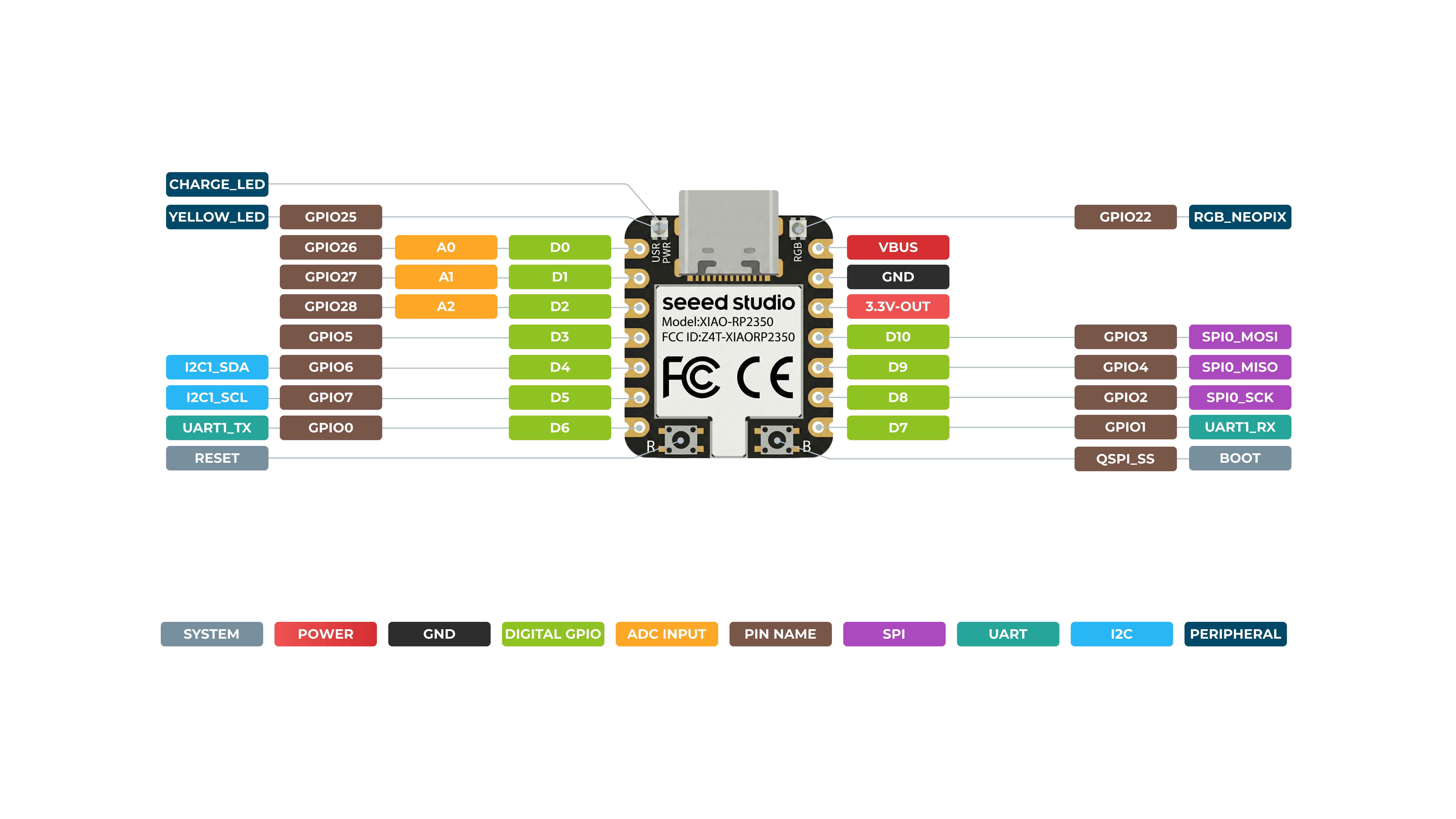
Hardware Overview
Front
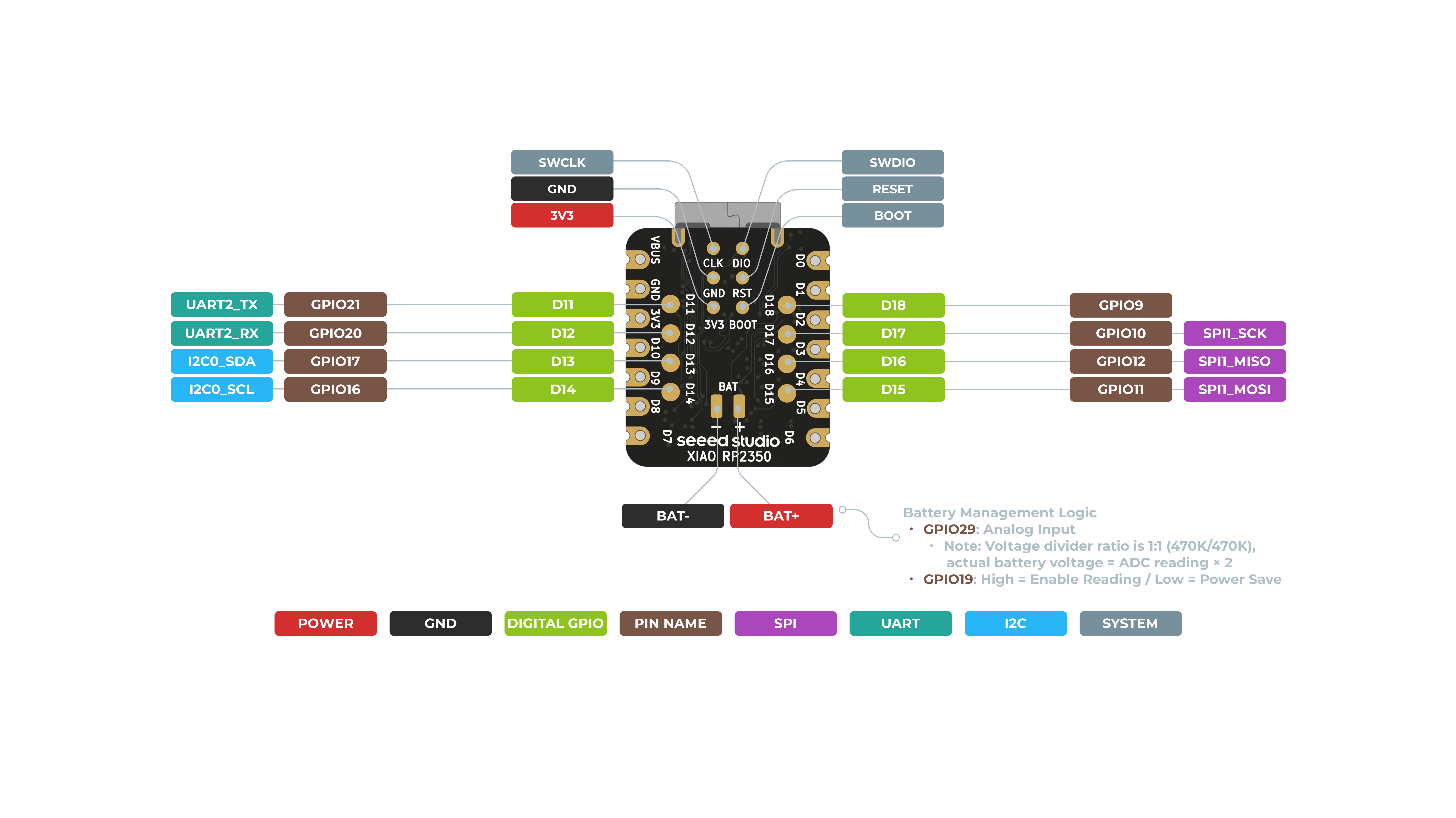
Back
Need more details on pinouts? Navigate to Assets and Resources below.
Pin Map
| XIAO Pin | Function | Chip Pin | Alternate Functions | Description |
|---|---|---|---|---|
| 5V | VBUS | Power Input/Output | ||
| GND | ||||
| 3V3 | 3V3_OUT | Power Output | ||
| D0 | Analog | GPIO26 | GPIO, ADC | |
| D1 | Analog | GPIO27 | GPIO, ADC | |
| D2 | Analog | GPIO28 | GPIO, ADC | |
| D3 | SPI0_CSn | GPIO5 | GPIO, SPI | |
| D4 | SDA1 | GPIO6 | GPIO, I2C Data | |
| D5 | SCL1 | GPIO7 | GPIO, I2C Clock | |
| D6 | TX0 | GPIO0 | GPIO, UART Transmit | |
| D7 | RX0 | GPIO1 | GPIO, UART Receive | |
| D8 | SPI0_SCK | GPIO2 | GPIO, SPI Clock | |
| D9 | SPI0_MISO | GPIO4 | GPIO, SPI Data | |
| D10 | SPI0_MOSI | GPIO3 | GPIO, SPI Data | |
| D11 | RX1 | GPIO21 | GPIO, UART Receive | |
| D12 | TX1 | GPIO20 | GPIO, UART Transmit | |
| D13 | SCL0 | GPIO17 | GPIO, I2C Clock | |
| D14 | SDA0 | GPIO16 | GPIO, I2C Data | |
| D15 | SPI1_MOSI | GPIO11 | GPIO, SPI Data | |
| D16 | SPI1_MISO | GPIO12 | GPIO, SPI Data | |
| D17 | SPI1_SCK | GPIO10 | GPIO, SPI Clock | |
| D18 | SPI1_Csn | GPIO9 | Csn | |
| ADC_BAT | GPIO29 | Read the BAT voltage value | ||
| ADC_BAT_EN | GPIO19 | BAT voltage detect enable | ||
| Reset | RUN | RUN | ||
| Boot | RP2040_BOOT | Enter Boot Mode | ||
| CHARGE_LED | NCHG | CHG-LED_Red | ||
| RGB LED | GPIO22 | RGB LED | ||
| USER_LED | GPIO25 | User Light_Yellow |
Prerequisites
To get started, ensure you have:
- An RP2350 board
- The Arduino IDE
- A USB cable
Setting Up the Software
1. Install the Arduino IDE
Download and install the latest Arduino IDE from the official site: Arduino Software.
2. Add RP2350 Board Support
-
Open the Arduino IDE and navigate to File > Preferences.
-
In the Additional Boards Manager URLs field, add this URL:
https://github.com/earlephilhower/arduino-pico/releases/download/global/package_rp2040_index.json
-
Click OK to save your settings.
-
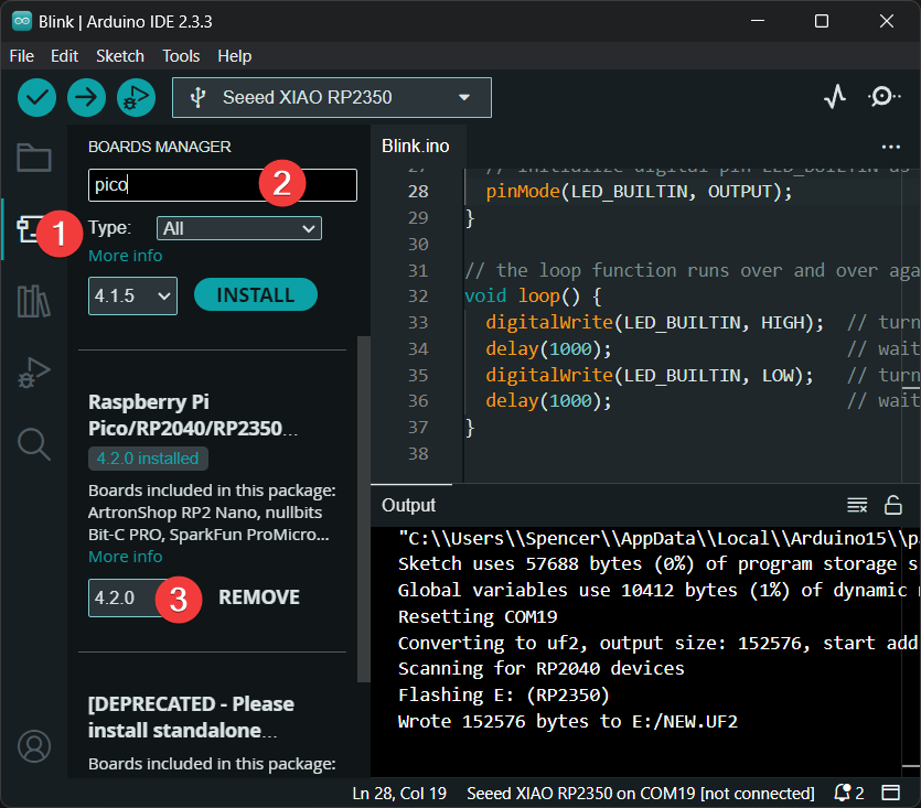
Go to Tools > Board > Boards Manager.
-
In the Boards Manager, search for pico and click Install.
-
After installation, go to Tools > Board and select the board shown below as your board.
Ensure you install version 4.2.0 or later for full support of the XIAO RP2350 board.
3. Uploading a Sketch
Before uploading a sketch, place your XIAO RP2350 into BOOT mode. Use one of the methods below:
- Method 1: Before Connecting to Computer
- Method 2: While Connected to Computer
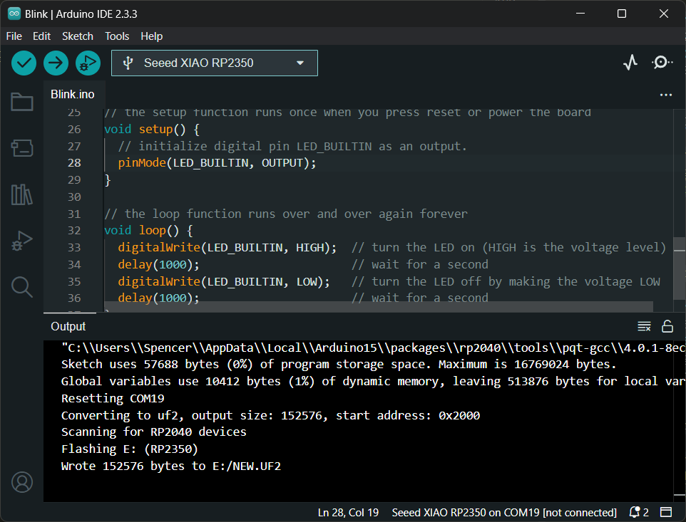
- Open the Arduino IDE and create a new sketch.
- Write your code. For example, use the
Blinkexample code. - Go to Tools > Port and select the port where your RP2350 is connected.
Low Power Performance Verification
The power supply design of XIAO RP2350 delivers excellent performance in low-power scenarios and can be widely applied to various low-power applications.
Battery Connection
The XIAO RP2350 can be powered by a 3.7V lithium battery. You can refer to the diagram below for wiring.
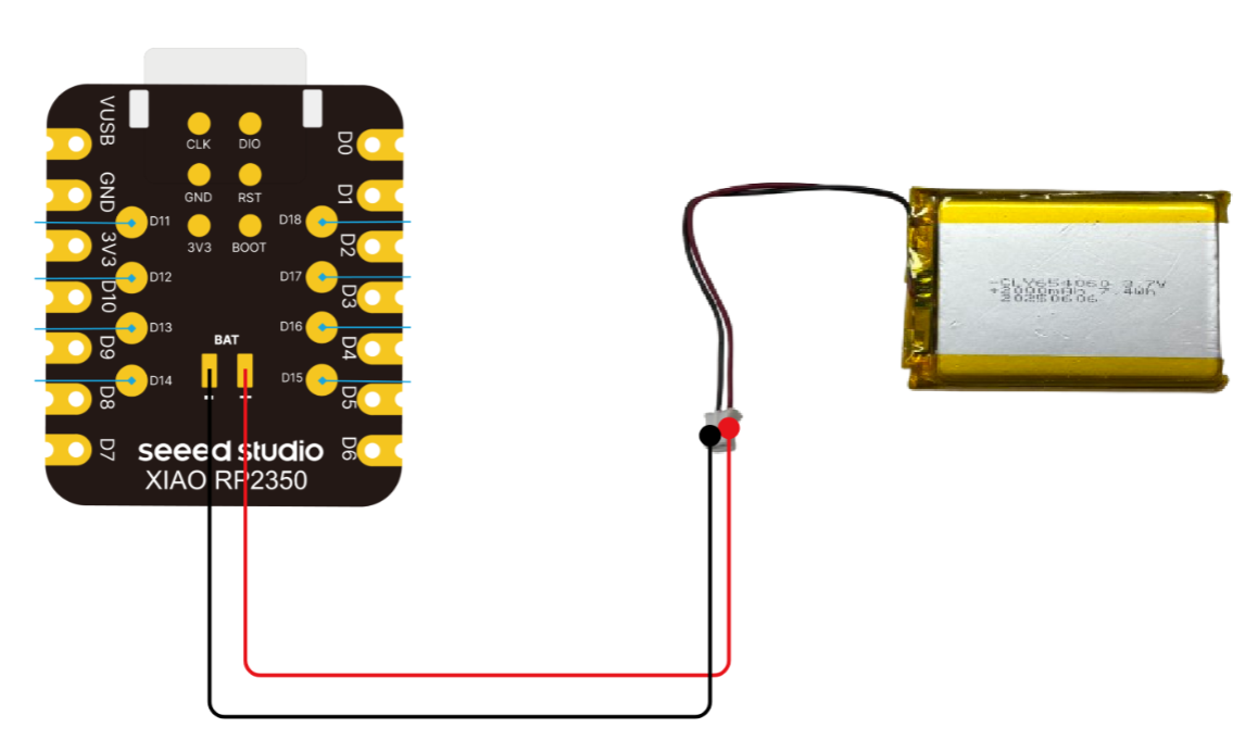
Please be careful not to short-circuit the positive and negative terminals and burn the battery and equipment when soldering.
Flash the firmware
You can use our pre-written firmware for verification and performance testing.
Download XIAO RP2350 Low Power Test Firmware, drag it into the file system.
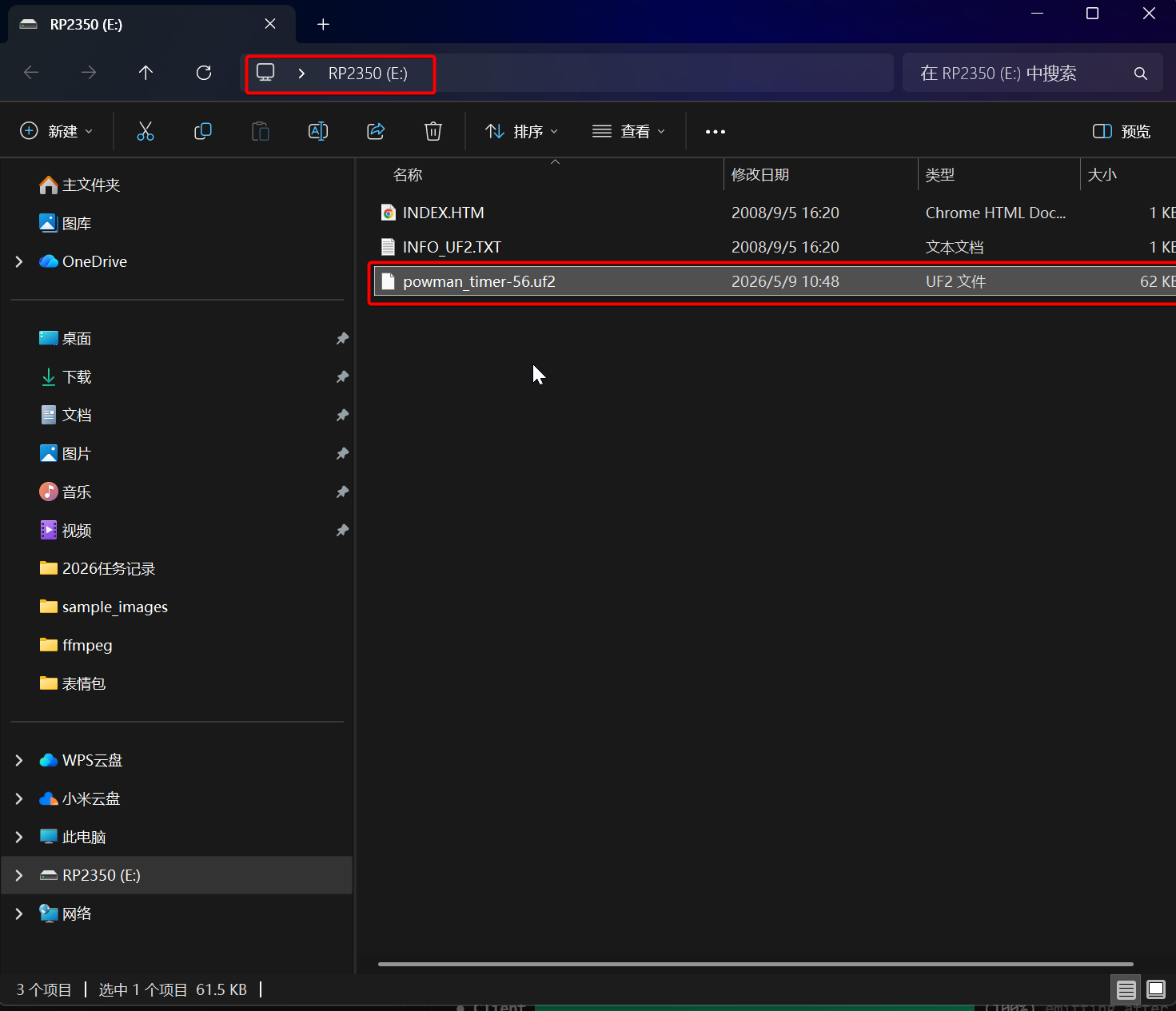
This UF2 firmware is compiled from a third-party source. For the firmware source code, please refer to: pico-examples/powman/powman_timer
This firmware source code depends on the pico-sdk. Before use, you need to download the relevant toolchain in a Linux environment following the steps in the pico-sdk README.
Please note that due to the rapid updates of pico-sdk and the toolchain, you may encounter function parameter conflicts and other compilation errors (this example library is not maintained as an official Raspberry Pi library, and there may be version and environment gaps). If you only need to verify the low-power capability of XIAO RP2350, it is recommended to use the UF2 firmware directly for quick and convenient testing.
Result
After instrumental testing and verification, the average current of the XIAO RP2350 is 53 μA when entering low-power mode.
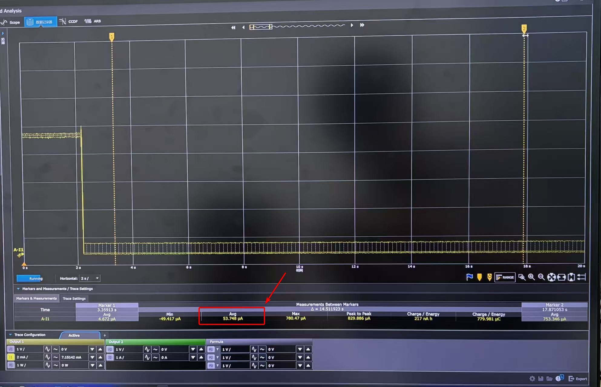
- The average current in low-power mode measured by different instruments may vary. Please refer to the actual test results.
- This test result is obtained after flashing the low-power test firmware.
- For power consumption testing, the test wiring shall be connected to the BAT interface on the back side.
- Since the Arduino IDE has difficulty integrating the pico-extras library (which contains pico/sleep.h required for deep sleep), it is recommended to use the Pico SDK or the PlatformIO + arduino-pico framework for ultra-low-power development.
Assets & Resources
Hardware Design
- 📄[Datasheet] Raspberry Pi RP2350 Datasheet
- 📄[Schematic] XIAO RP2350 Schematic
- 🗃️[PCB Design Files] XIAO RP2350 KiCad Project
- 🗃️[PCB Design Libraries]
- 📄[Pinout Diagram] XIAO RP2350 Pinout Sheet
Mechanical Design
- 📄[2D Dimensions] XIAO RP2350 Dimension in DXF
- 🔗[3D Model] XIAO RP2350 3D Model
Software & Tools
- 📄[Test Firmware] XIAO RP2350 Low Power Test Firmware
Others
- 📄[Document] Getting Started with Raspberry Pi Pico-series
- A comprehensive guide to setting up and programming Raspberry Pi Pico boards, ideal for beginners looking to learn MicroPython or C/C++.
- 📄[Document] Raspberry Pi Pico-series Python SDK
- The book which documents the MicroPython setup tutorials and APIs
- 📄[Document] Raspberry Pi Pico-series C/C++SDK
- The book which documents the Pico C/C++ SDK APIs
- 📄[arduino-pico GitHub](https://github.com/earlephilhower/arduino-pico)
- 📄[Arduino-Pico Core Documentation](https://arduino-pico.readthedocs.io/en/latest/install.html)
Support & Discussion
Thank you for using Seeed products! We offer multiple channels for support and community discussion: