Spartan Edge Accelerator Board

The Spartan Edge Accelerator Board (SEA Board in short) is a lightweight FPGA development board, it is based on the Xilinx Spartan-7 chip and follows the Arduino shield form factor. Hence, you can use it as an Arduino shield to driver an LCD and a camera or as a stand-alone FPGA development board. Besides, with the help of on-board ESP32 chip, the SEA board also enables your Arduino with WiFi and Bluetooth function.
Spartan-7 is the newest and most cost-effective FPGA chip among Xilinx’s FPGA family, offers the best in class performance per watt.
On top of that, we provide the full FPGA APIs for Arduino, which means Arduino users are able to use the FPGA function without knowing anything about FPGA. This board will broaden Arduino’s capability in many ways like simple image processing and computer vision application, signal encryption and decryption, and signal sampling and processing.
Features
High-speed image processing
- Integrated mipi, mini HDMI interface
- Supports Raspberry Pi camera v1.0 (OV5640)
- Maximum support for 30fps image transmission
Encrypted Internet of Things
- IoT WiFi and Bluetooth with ESP32
- Support AWS, Azure and other cloud services
- Support software encryption algorithm
Multiple I/O port extensions
- 20 user-defined extended I/O ports(Stand-alone mode)
- 10 user-defined extended I/O ports(Arduino shield mode)
- Full FPGA APIs for Arduino
Onboard functional modules
- 8-bit ADC & DAC
- 6-axis accelerometer & gyroscope
- 2 user RGB LEDs & buttons
Two customized development modes
- Arduino Shield Mode
- FPGA Stand Alone Mode
Remarks: Users can choose different pin headers according to different needs and solder the pins according to their development needs.
Target users
- Arduino Developers
- IoT Developers
- FPGA Developers
Applicable Cases
- MIPI camera input and HDMI output Vivado engineering
- On-board LED, DIP switch, ADC and DAC reference case
- Onboard gyroscope case
- Provide GPIO/UART/ADC/DAC/RGB-LED expansion for Arduino
- Signal generator case (requires Arduino configuration)
- ESP32 controlled signal generator case
- Use the AWS GreenGrass IoT platform case
- Color recognition and object tracking case
- Graphic recognition case (triangle, circle and square recognition)
- Digital Character Recognition Case
- AES encryption and decryption algorithm implementation in FPGA
- Implementation of the PID algorithm in the FPGA
New applications will be updated.............
For more case resources, please visit this Github page.
Specifications
Parameter | Value |
FPGA | |
FPGA Chip | Spartan-7 XC7S15 |
Logic Cells | 12,800 |
Slics | 2000 |
CLB Flip-Flops | 16000 |
Max. Distributed RAM (Kb) | 150 |
Block RAM/FIFO w / ECC (36 kb each) | 10 |
Max. Distributed RAM (Kb) | 150 |
Total Block RAM (Kb) | 360 |
Max. Distributed RAM (Kb) | 150 |
Clock Mgmt Tiles (1 MMCM + 1 PLL) | 2 |
DSP Slices | 20 |
Wireless | |
Wireless Chip | Espressif ESP32-D0WDQ6 |
WiFi | 802.11 b/g/n 2.4GHz |
Bluetooth | Bluetooth 4.1 with BLE |
Peripheral | |
Video | Mini HDMI x1 |
Camera | CSI/MIPI interface x1 (compatible with Raspberry Pi Camera V1 - OV5640) |
SD card | 20 |
DSP Slices | Micro SD/TF card slot x1 |
FPGA GPIO | 10 pins header (IO9~IO0) |
Arduino GPIO | 32 pins header (Arduino form factor) |
Grove | Grove Connector x2 (I2C/D2) |
LED | Monochrome LED x2 |
Button | Boot x1 |
Switch | Power Mode Switch x1 |
Power | |
Operating Voltage | 5V |
IO Voltage | 5V |
Power Mode | USB Type C 5V |
Other | |
ADC | 8 bit ADC1173 |
Accelerometer and Gyroscope | 6-axis LSM6DS3TR |
The SEA shield's IO voltage is 5V, and the FPGA's IO voltage is 3.3V, so we made a voltage divider to make the IOs voltage compatible. The 3.3V IO voltage of the SAM D21 series will be less than 3.3V after voltage division, which is not enough to drive the FPGA's IO. Therefore, at present, the SEA development board only supports the 5V IO Arduino board, such as Arduino UNO and Seeeduino V4.2.
Hardware Overview
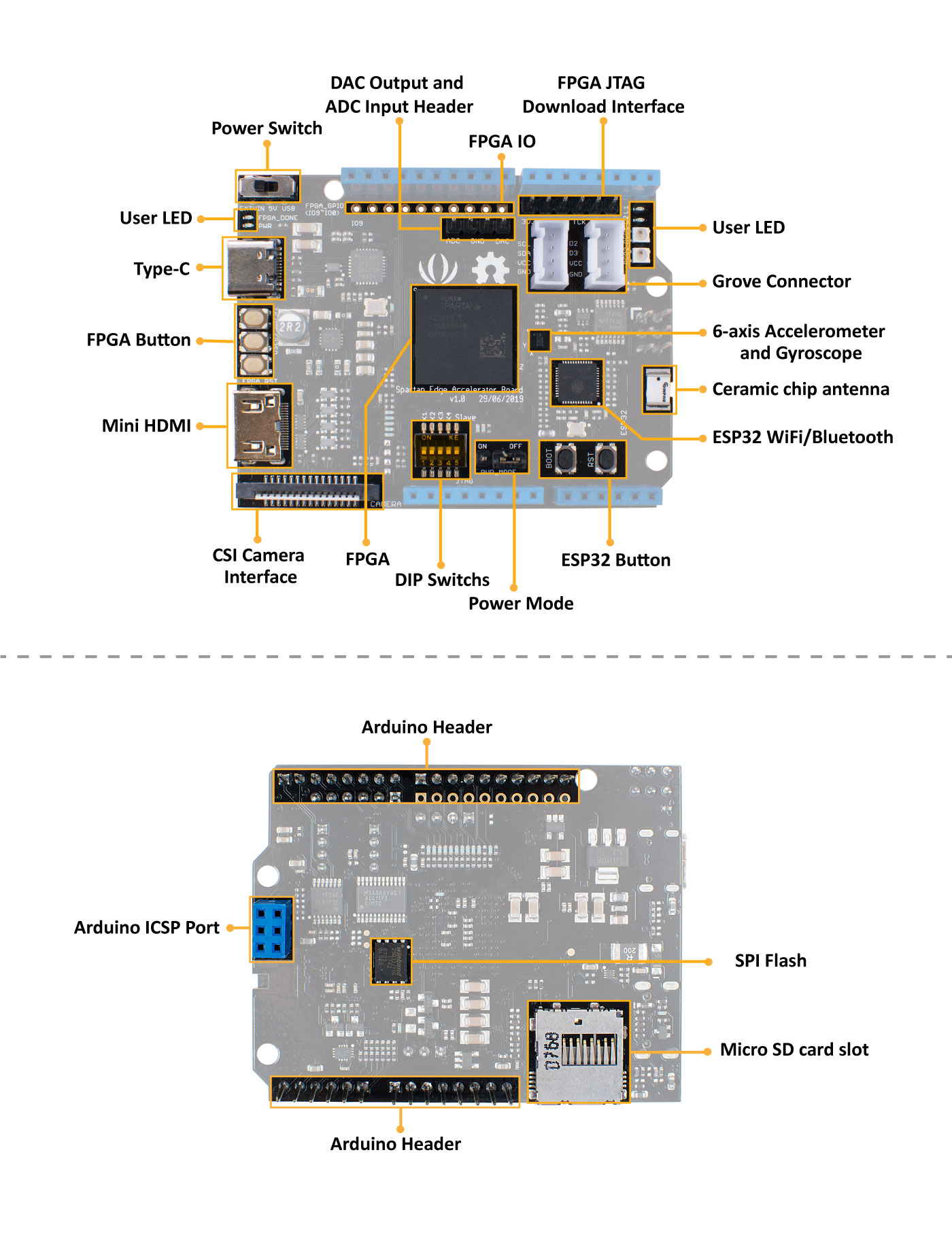
Number | Detail |
1 | FPGA : XC7S15-1FTGB196C |
2 | WiFi/Bluetooth : ESP32-D0WDQ6 |
3 | 6-axis Accelerometer and Gyroscope : LSM6DS3TR |
4 | DAC : DAC7311IDCKR |
5 | Buck-DCDC : TPS62130 |
6 | USB-to-UART : CP2102-GMR |
7 | USB : Type-C |
8 | Mini HDMI |
9 | CSI Interface :MIPI Camera (compatible with Raspberry Pi Camera V1 - OV5640) |
10 | Arduino Header : Compatible with Arduino UNO |
11 | DIP Switchs : |
12 | ESP32 Button :Boot and RST |
13 | FPGA Button :USER1 USER2 FPGA_RST |
14 | User LED: L1/L2/RGB1/RGB2 |
15 | Power Switch : |
16 | Power Mode: |
17 | DAC Output and ADC Input Header |
18 | FPGA IO : IO9~IO0 |
19 | FPGA JTAG Download Interface |
20 | Grove Connector : 1x I2C; 1x D2&D3 |
21 | Ceramic chip antenna |
22 | ADC : ADC1173 |
23 | SPI Flash : W25Q32JVZPIG |
24 | Analog Switch :DG2788A |
25 | LDO : XC6221B102MR |
26 | LDO : RT9013-18GB |
27 | LDO : CJ1117-3V3 |
28 | SD card slot : Micro SD/TF card |
Getting Started
Spartan Edge Accelerator Board can work in two modes:
- Arduino shield Mode
- Stand-alone Mode
In brief, it can work as a Arduino shield to bring the Arduino FPGA and Wireless features, it also can work as a FPGA development board without an Arduino.
Arduino shield Mode
In this wiki, we use Seeeduino V4.2, you can also use Arduino UNO, they are fully compatible with each other.
Hardware
Materials required
- Seeeduino V4.2 x1
- Spartan Edge Accelerator Board x1
- Micro SD card or TF card x1
- USB Type C data cable x1
Hardware Connection
- Step1. Insert the Micro SD card or TF card into the SD card slot
- Step2. Plug the SEA Board into the Arduino
- Step3. Use one of the following three methods to power the system
Power Port | Input Voltage | Power Switch Position | Power Mode Position |
Powered by SEA board USB Type C port | 5V DC | USB | ON |
Powered by Seeeduino V4.2 micro USB port | 5V DC | - | ON |
Powered by Seeeduino V4.2 DC port | 8~17V DC | 5V | ON |

You can also power both the SEA board and the Arduino at the same time, but please make sure you have set the Power Mode Position to OFF. Only then, the system power will be isolated, and you can power the Arduino and SEA board separately.
Spartan Edge Accelerator Board ESP32 Boot
Firstly, to work with Arduino, we should load bitstream(FPGA Logic) from SD Card to the on-board FPGA(xc7s15). The following library will show you how to do this via on-board ESP32.
a library for Spartan Edge Accelerator Board
The purpose of this library is to load bitstream(FPGA Logic) from SDCard to the on-board FPGA(xc7s15) by the on-board ESP32.
The software development environment is Arduino IDE with ESP32 Boards support.
Since Version 1.6.4, Arduino allows installation of third-party platform packages using Boards Manager. We have packages available for Windows, Mac OS, and Linux (32 and 64 bit).
- Install the current upstream Arduino IDE at the 1.8 level or later. The current version is at the Arduino website.
- Start Arduino and open Preferences window.
- Enter
https://dl.espressif.com/dl/package_esp32_index.jsoninto Additional Board Manager URLs field. You can add multiple URLs, separating them with commas. - Open Boards Manager from Tools > Board menu and install esp32 platform (and don't forget to select your ESP32 board from Tools > Board menu after installation).
- select tool->board->DOIT ESP32 DEVKIT
Stable release link: https://dl.espressif.com/dl/package_esp32_index.json
Development release link: https://dl.espressif.com/dl/package_esp32_dev_index.json
If you want more details, you can click the link
Library Usage
- 1.Download the ESP32 Boot Library

Then add this library to your Arduino IDE.
If you don't know how to install the library, please kindly check:
Installing Additional Arduino Libraries
You can find two example folders in this library

Example | Description |
01LoadDefaultBitstream | This example will load SDCard file /overlay/default.bit to FPGA |
02LoadConfigBitstream | This example will read a ini format file /board_config.ini in SDCard,then load the bitstream spcified by the value of key overlay_on_boot to FPGA. |
- 2.Prepare SDCard
2.1 Format the SDCard with FAT16/FAT32 filesystem.

2.2 Create a top level subfolder named overlay in the SDCard.
2.3 Put your bitstream or sample bitstream files (must have a extend name .bit) into the folder overlay.
The sample bitsteam : GPIO extension controlled by SPI interface, with support of ADC/DAC/RGB-LED, see source code.
2.4 If you run example 01LoadDefaultBitstream, rename the bitstream file in overlay to default.bit.

2.5 If you run example 02LoadConfigBitstream, put board_config.ini into SDCard root folder.
2.6 Insert the SDCard to the Spartan (Edge Accelerator) Board.
-
3.Upload example
3.1 Connect the Spartan Board through USB Type-C wire to the PC, and install USB232 driver (chip CP2102).
3.2 Turn the power switch (near the USB Type-C slot) to USB side to power on the board.
3.3 Open one of the library examples by Arduino IDE.
3.4 Check Board & Port setting in Arduino IDE as described in last section.
3.5 Press 'BOOT' Button on Sparton Board and last more than 1 seconds to force ESP32 enter Bootloader mode.
3.6 Press 'Upload' button in Arduino IDE to upload the example ('s compiled binary) to ESP32. -
4.Run example
4.1 Make sure the on-board DIP-switch K5 (last one) on Slave(ON) side, which enable FPGA programing by other device(MCU).
4.2 Press 'RST' button on Spartan Board to startup the example.
4.3 After the example bootup a few seconds, the FPGA_DONE(red color) LED on the board will light on.
Spartan Edge Accelerator Board IO Example
Then, the following tutorial will show you how to control the GPIO/ADC/DAC/RGB-LED resources of Spartan Edge Accelerator Board with Arduino.
- Download the IO Example Library:

- Add this library to your Arduino IDE. If you don't know how to install the library, please kindly check:
Installing Additional Arduino Libraries
-
Located to the
examplesfolder, choose any example, double cilck the .ino file. -
Upload the demo. If you do not know how to upload the code, please check How to upload code.
Stand-alone Mode
Hardware
Materials required
Just power the Spartan Edge Accelerator Board via the USB Type C cable.
Software
Spartan Edge Accelerator Board can also work as a traditional FPGA development board. The following traditional will show you how to use it at the stand-alone mode.
In this section, you will learn about the Project mode features for project creation, source file management, design analysis, constraint definition, and synthesis and implementation run management. This could be used as a quick reference.
First of all, you should download the vivado tutorial library, we will need some sorce files.

-
Step 1: Creating a Project
Launching Vivado
Creating a New Project
-
After Vivado opens, select Create Project on the Getting Started page.
-
Click Next in the New Project wizard
-
Specify the Project Name and Location (Select “Create project subdirectory” to create a folder for your project)
-
Click Next.
-
Select RTL Project as the Project Type and click Next.(Select Do not specify sources at this time and add your files soon afterwards)
(The Vivado Design Suite allows for different design entry points depending on your source file types and design tasks. You can choose the suitable type of project.)
-
Select the xc7s15ftgb196-1 part for project, and click Next, as shown in figure 1.
-
Click Finish

The Vivado IDE opens project_tutorial in the default layout, as shown in figure 2.

The Flow Navigator shows the basic design process clearly.
The Sources is made up of Constraints, Simulation Sources and Utility Sources.
The Design Runs creates synth_1 and impl_1 by default.
The running status of vivado is displayed in the upper right corner.
-
Step 2: Add and Create Your Files
in this step, we add test.v , test_pin.xdc , test_sim.v in our project. These files are located in different folders of vivado_tutorial/vivado_tutorial.srcs
-
Click Add Sources in the PROJECT MANAGER of the Flow Navigator to add RTL file.
-
Select Add or create design sources and click Next.
-
Click the button and select options or click the options directly to add or create files, as shown in figure 3.

- Here, we add RTL files directly. Select Add Files and add file test.v in your directory, as shown in figure 4.

-
Click Finish.
-
Click Add Sources in the PROJECT MANAGER of the Flow Navigator again to add constraints file.
-
Select Add or create constraints and click Next.
-
Click Add Files and add your constraints file test_pin.xdc ,as shown in figure 5

-
Click Finish.
-
Click Add Sources in the PROJECT MANAGER of the Flow Navigator again to add simulation file.
-
Select Add or create simulation sources and click Next.
-
Click Add Files and add your simulation file test_sim.v ,as shown in figure 6

-
Click Finish.
Finally, the file we added will appear in the Sources, as shown in figure 7.

-
Step 3: Elaborating the RTL Design
The Vivado IDE includes an RTL analysis and IP customizing environment. There are also several RTL Design Rule Checks (DRCs) to examine ways to improve performance or power on the RTL design.
-
Select Open Elaborated Design in the Flow Navigator to elaborate the design.
-
Ensure that the Layout Selector pull down menu in the main Toolbar has Default Layout selected. The Elaborated Design enables various analysis views including an RTL Netlist, Schematic, and Graphical Hierarchy. The views have a cross-select feature, which helps you to debug and optimize the RTL.
-
Explore the logic hierarchy in the RTL Netlist window and examine the Schematic. You can traverse the schematic by double-clicking on cells to push into the hierarchy, or by using commands like the Expand Cone or Expand/Collapse from the Schematic popup menu.
-
Select any logic instance in the Schematic and right-click to select the Go to Source or Go to Definition commands.
-
Click the Messages window at the bottom of the Vivado IDE, and examine the messages.
-
Click the Collapse All button in the Messages toolbar.
-
Expand the Elaborated Design and the messages, as shown in figure 8.

- Click one of the links and the Text Editor opens the RTL source file with the relevant line highlighted.
- Close the Text Editor windows.
- Close the Elaborated Design by clicking on the X on the right side of the Elaborated Design window banner, and click OK to confirm.
-
Step 4: Using the IP Catalog
The Xilinx IP Catalog provides access to the Vivado IP configuration and generation features. You can sort and search the Catalog in a variety of ways. IP can be customized, generated, and instantiated.
-
Click the IP Catalog button in the Flow Navigator, under Project Manager.
-
Browse the IP Catalog to examine the various categories and IP filtering capabilities.
-
Choose the corresponding IP and perform native customization and configuration of IP within the tool and select OK
-
Close the IP Catalog tab by clicking on the X on the window tab.
-
Step 5: Running Behavioral Simulation
The Vivado IDE integrates the Vivado Simulator, which enables you to add and manage simulation sources in the project. You can configure simulation options, and create and manage simulation source sets. You can run behavioral simulation on RTL sources, prior to synthesis.
- In the Flow Navigator, under Project Manager, click the Settings command. The Settings dialog box opens with Project Settings at the top, and Tool Settings below that, as shown in figure 9.

- Examine the settings available on the Simulation page, then click Cancel to close the dialog box.
- Click the Run Simulation command in the Flow Navigator, then click the Run Behaviora Simulation in the sub-menu, as shown in figure 10.

- Drag the bar to the left and use these tools to zoom in or zoom out to see the appropriate image, as shown in figure 11 and figure 12.


- Click X on the Right-Up corner of figure 13 and click OK to close the SIMULATION.

-
Step 6: Reviewing Design Run Settings
Design runs are a way of configuring and storing the many options available in the different steps of the synthesis and implementation process. You can configure these options and save the configurations as strategies to be used in future runs.
-
In the Flow Navigator, under Project Manager, click the Settings command.
-
Select the Synthesis page under Project Settings. For a complete description of these options, see the Vivado Design Suite User Guide: Synthesis(UG901).
-
Select the Implementation page under Project Settings. For a complete description of these options, see the Vivado Design Suite User Guide: Implementation(UG904).
-
Step 7: Synthesizing and Implementing the Design
After configuring the synthesis and implementation run options, you can run synthesis and run implementation in the Design Runs or click the button or click corresponding buttons in the Flow Navigator to do this. The running status of vivado is displayed in the upper right corner while Synthesizing and Implementing.
For this tutorial, we will run these steps in the Design Runs.
- Right click the syth_1 and select Launch Runs, as shown in figure 14.

- Click ok and running status is displayed in the upper right corner, as shown in figure 15.

- Click Open Synthesized Design for further design and analysis. You can see Report Timing Summary , Report Utilization and others, as shown in figure 16.

- Run Implementation in the same way, as shown in figure 17.

- Click Open implemented Design to see reports after implementation
-
Step 8: Generating a Bitstream File
After Implementing the Design, we can see synthesis and implement Complete in the Design Runs,as shown in figure 18.

Click Generate Bitstream in the Flow Navigator.
-
Step 9: Download the file
After Generate Bitstream, you have two ways to load the file to FPGA.
You can use the JTAG interface(on the Right-Up corner of figure 19) to load the bit file to FPGA in vivado, or use the ESP32 (on the Right-Down corner of figure 19) to load the bit file to FPGA.

Follow below steps, to load bitstream to FPGA through JTAG interface
-
Power the board and connect the Platform Cable USB II (Or Compatible Cable).
-
Click Open Target and Auto Connect in the Flow Navigator.
-
While connect to the board successfully, click Program Device and choose the bit file and click Program, as shown in figure 20

-
After download the bit file, the FPGA_DONE led will light.
In this project, if you press any key or both of them(USER1 and USER2), LED L1 will go out.
Schematic Online Viewer
Resources
- [PDF] Spartan-7 FPGAs Datasheet
- [PDF] ESP32 Datasheet
- [PDF] Spartan-Edge-Accelerator-Board Eagle File
Tech Support & Product Discussion
Thank you for choosing our products! We are here to provide you with different support to ensure that your experience with our products is as smooth as possible. We offer several communication channels to cater to different preferences and needs.