XIAO nRF52840(sense) With Zephyr(RTOS)
What is RTOS
One of the most important components of today's embedded systems is the RTOS also known as Real-Time Operating System, which is responsible for everything from task scheduling to performing applications.
RTOS is designed to provide a predictable execution mode. When the processing must meet the time limit of the system, RTOS is used. Therefore, compared with GPOS (General Purpose Operating System), RTOS is usually light in weight and small in size, and generally only provides functions required to run specific types of applications on specific hardware. In some cases, developers can modify the existing RTOS, narrow it down to only provide the functionality required by a specific application, and/or customize its functionality or performance characteristics.
What is Zephyr
The Zephyr OS is based on a small-footprint kernel designed for use on resource-constrained and embedded systems: from simple embedded environmental sensors and LED wearables to sophisticated embedded controllers, smart watches, and IoT wireless applications.
Feature
Zephyr offers a large and ever growing number of features including:
Extensive suite of Kernel services
Zephyr offers a number of familiar services for development:
- Multi-threading Services for cooperative, priority-based, non-preemptive, and preemptive threads with optional round robin time-slicing. Includes POSIX pthreads compatible API support.
- Interrupt Services for compile-time registration of interrupt handlers.
- Memory Allocation Services for dynamic allocation and freeing of fixed-size or variable-size memory blocks.
- Inter-thread Synchronization Services for binary semaphores, counting semaphores, and mutex semaphores.
- Inter-thread Data Passing Services for basic message queues, enhanced message queues, and byte streams.
- Power Management Services such as overarching, application or policy-defined, System Power Management and fine-grained, driver-defined, Device Power Management.
Multiple Scheduling Algorithms
Zephyr provides a comprehensive set of thread scheduling choices:
- Cooperative and Preemptive Scheduling
- Earliest Deadline First (EDF)
- Meta IRQ scheduling implementing “interrupt bottom half” or “tasklet” behavior
- Timeslicing: Enables time slicing between preemptible threads of equal priority
- Multiple queuing strategies:
- Simple linked-list ready queue
- Red/black tree ready queue
- Traditional multi-queue ready queue
Bluetooth Low Energy 5.0 support
Bluetooth 5.0 compliant (ESR10) and Bluetooth Low Energy Controller support (LE Link Layer). Includes Bluetooth mesh and a Bluetooth qualification-ready Bluetooth controller.
- Generic Access Profile (GAP) with all possible LE roles
- Generic Attribute Profile (GATT)
- Pairing support, including the Secure Connections feature from Bluetooth 4.2
- Clean HCI driver abstraction
- Raw HCI interface to run Zephyr as a Controller instead of a full Host stack
- Verified with multiple popular controllers
- Highly configurable
Mesh Support:
- Relay, Friend Node, Low-Power Node (LPN) and GATT Proxy features
- Both Provisioning bearers supported (PB-ADV & PB-GATT)
- Highly configurable, fitting in devices with at least 16k RAM
Reference: Zephyr Project
Getting Started
Once the Zephyr toolchain has been setup and an associated SDK has been downloaded you can begin application development.
For the Xiao nrf52840 the board description file can be referenced for further setup information.
To program the Xiao nrf52840 the following steps can be taken:
- Build an example or your application
- Plugin the Xiao nrf52840
- Double click the
RSTbutton setting the device into uf2 bootloader mode - Run the command
west flash -r uf2to flash the device
The simplest example is to run the "Hello World" sample on the board. After changing to the directory of the Zephyr install run the following commands.
west build -p always -b xiao_ble samples/hello_world
If you're using a Xiao nRF52840 Sense board you can build for its board definition file by using xiao_ble/nrf52840/sense in place of xiao_ble like so (for this example it makes no difference):
west build -p always -b xiao_ble/nrf52840/sense samples/hello_world
After this completes enter uf2 bootloader mode and type:
west flash -r uf2
Find the port for your device, in the case of Ubuntu this can be done via: ls /dev/tty* and confirming which device appears when your USB has been plugged in.
In my example I see /dev/ttyACM0:
Using screen you can then connect and monitor the serial response:
screen /dev/ttyACM0 115200
You should see a response similar to the following:
*** Booting Zephyr OS build v3.6.0-5403-gd9e2b0c70763 ***
Hello World! xiao_ble/nrf52840
To assist with the process of using Zephyr with Xiao and its expansion board a repository has been constructed with several overlays and configurations used here. The commands included in this wiki article assume it is located ../applications/xiao-zephyr-examples relative to the zephyr root. An alternative path can be provided to the commands below by updating it.
git clone https://github.com/Cosmic-Bee/xiao-zephyr-examples
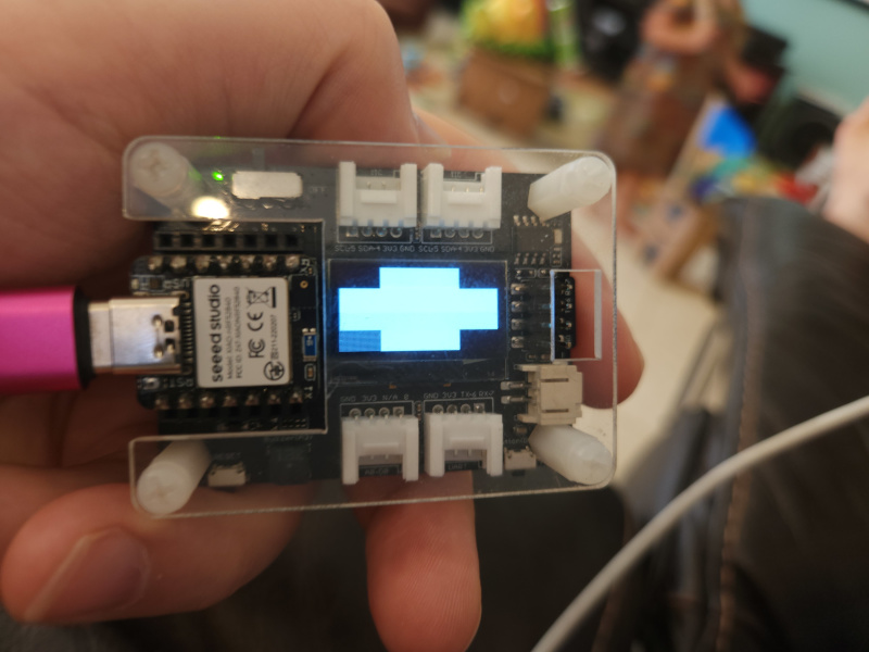
Hardware Preparation
| Seeed Studio XIAO nrf52840 Sense | Seeed Studio Expansion Board |
|---|---|
 |  |
Developer Knowledge
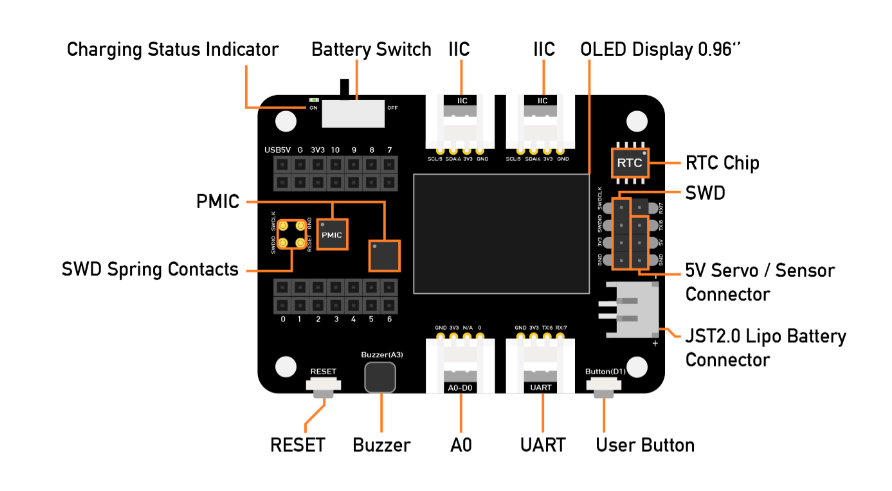
XIAO Expansion Board
In order to use Grove modules with Seeed Studio XIAO nrf52840, we will use a Seeed Studio Expansion Base for XIAO and connect XIAO nrf52840 on it.
After that, the Grove connectors on the board can be used to connect Grove modules
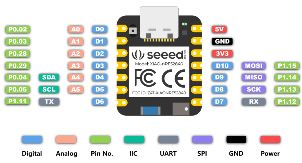
Pin Definitions
You need to follow the graphic below to use the appropriate internal pin numbers when connecting the Grove modules to the Grove connectors on Grove Shield for Seeed Studio XIAO.
Primary Functionality
- Onboard LED
- Onboard IMU (Sense)
- Onboard Mic (Sense)
- Bluetooth
- TFLite
Onboard LED
For this example we'll use the blinky sample to blink the onboard LED.
cd ~/zephyrproject/zephyr
west build -p always -b xiao_ble samples/basic/blinky
Double press the RESET button and then flash:
west flash -r uf2
You will see the onboard red LED toggle on and off creating a blinking effect.
Let's dive into this example a bit to see why it works.
The associated example code reference led0:
#define LED0_NODE DT_ALIAS(led0)
static const struct gpio_dt_spec led = GPIO_DT_SPEC_GET(LED0_NODE, gpios);
This is defined in the Xiao nRF52840 devicetree code via an alias:
 aliases {
  led0 = &led0;
 };

 leds {
  compatible = "gpio-leds";
  led0: led_0 {
   gpios = <&gpio0 26 GPIO_ACTIVE_LOW>;
   label = "Red LED";
  };
  ...
  }
It corresponds with the 26 pin on the board.
For the pins with the Xiao breakut you don't need to use the &gpio0 pin mapping directly as the board files provide a Xiao connector which simplifies the interface.
For example if I were to reference D0 I'd reference it either as &gpio 2 or &xiao_d 0.
/ {
 xiao_d: connector {
  compatible = "seeed,xiao-gpio";
  #gpio-cells = <2>;
  gpio-map-mask = <0xffffffff 0xffffffc0>;
  gpio-map-pass-thru = <0 0x3f>;
  gpio-map
   = <0 0 &gpio0 2 0>  /* D0 */
   , <1 0 &gpio0 3 0>  /* D1 */
   , <2 0 &gpio0 28 0>  /* D2 */
   , <3 0 &gpio0 29 0>  /* D3 */
   , <4 0 &gpio0 4 0>  /* D4 */
   , <5 0 &gpio0 5 0>  /* D5 */
   , <6 0 &gpio1 11 0>  /* D6 */
   , <7 0 &gpio1 12 0>  /* D7 */
   , <8 0 &gpio1 13 0>  /* D8 */
   , <9 0 &gpio1 14 0>  /* D9 */
   , <10 0 &gpio1 15 0>  /* D10 */
   ;
 };
};
Onboard IMU (Sense)
One of the main features of the Xiao nrf52840 is its built in IMU sensor. With this data one could train a machine learning model, detect gestures, movement of the board, etc.
To test this feature we'll use a built in sample that utilizes the IMU and then look into the associated code around why it works.
cd ~/zephyrproject/zephyr
west build -p -b xiao_ble/nrf52840/sense samples/sensor/lsm6dsl
Double press the RESET button and then flash:
west flash -r uf2
Next you'll need to connect to see the output:
screen /dev/ttyACM0 115200
This should display something along these lines:
3LSM6DSL sensor samples:

accel x:1.330409 ms/2 y:-1.705484 ms/2 z:9.957133 ms/2
gyro x:0.049632 dps y:-0.070860 dps z:-0.006184 dps
loop:46 trig_cnt:9677

3LSM6DSL sensor samples:

accel x:1.314257 ms/2 y:-1.734198 ms/2 z:9.902696 ms/2
gyro x:-0.220216 dps y:0.032833 dps z:-0.000458 dps
loop:47 trig_cnt:9892

3LSM6DSL sensor samples:

accel x:1.414158 ms/2 y:-1.476371 ms/2 z:9.835697 ms/2
gyro x:0.035430 dps y:-0.132252 dps z:-0.007788 dps
loop:48 trig_cnt:10107
Why does it work? We can see the sample code via the github repository for Zephyr.
const struct device *const lsm6dsl_dev = DEVICE_DT_GET_ONE(st_lsm6dsl);
The sample logic finds the associated st_lsm6dsl devicetree object for the target board. We can view the Xiao nrf52840 sense devicetree to see further how that's configured:
 lsm6ds3tr-c-en {
  compatible = "regulator-fixed-sync", "regulator-fixed";
  enable-gpios = <&gpio1 8 (NRF_GPIO_DRIVE_S0H1 | GPIO_ACTIVE_HIGH)>;
  regulator-name = "LSM6DS3TR_C_EN";
  regulator-boot-on;
  startup-delay-us = <3000>;
 };
&i2c0 {
 compatible = "nordic,nrf-twim";
 /* Cannot be used together with spi0. */
 status = "okay";
 pinctrl-0 = <&i2c0_default>;
 pinctrl-1 = <&i2c0_sleep>;
 pinctrl-names = "default", "sleep";
 clock-frequency = <I2C_BITRATE_FAST>;

 lsm6ds3tr_c: lsm6ds3tr-c@6a {
  compatible = "st,lsm6dsl";
  reg = <0x6a>;
  irq-gpios = <&gpio0 11 GPIO_ACTIVE_HIGH>;
  status = "okay";
 };
};
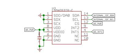
A GPIO is being used to enable the pin power. You can see from the definition file that it's using GPIO1 8. I've highlighted the relevant part of the Xiao nRF52840 schematic below:
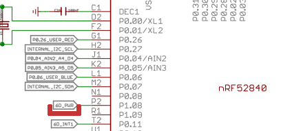
From this schematic highlight you can see GPIO1 8 is the enable pin for the IMU. In addition GPIO0 11 is the interrupt pin. As such this is reflected in the above devicetree snippet
Onboard Mic (Sense)
One of the main features of the Xiao nrf52840 is its built in mic. Like its IMU it allows for many machine learning applications through its use.
To test this feature we'll use a built in sample that utilizes the mic and then look into the associated code around why it works.
cd ~/zephyrproject/zephyr
west build -p -b xiao_ble/nrf52840/sense samples/drivers/audio/dmic
Double press the RESET button and then flash:
west flash -r uf2
Next you'll need to connect to see the output:
screen /dev/ttyACM0 115200
This should display something along these lines:
[00:00:00.297,088] <inf> dmic_sample: PCM output rate: 16000, channels: 1
[00:00:00.297,119] <inf> dmic_nrfx_pdm: PDM clock frequency: 1280000, actual PCM rate: 16000
[00:00:00.397,216] <inf> dmic_sample: 0 - got buffer 0x20008380 of 3200 bytes
[00:00:00.497,222] <inf> dmic_sample: 1 - got buffer 0x20006a80 of 3200 bytes
[00:00:00.597,229] <inf> dmic_sample: 2 - got buffer 0x20005180 of 3200 bytes
[00:00:00.697,235] <inf> dmic_sample: 3 - got buffer 0x20008380 of 3200 bytes
[00:00:00.797,241] <inf> dmic_sample: 4 - got buffer 0x20006a80 of 3200 bytes
[00:00:00.897,247] <inf> dmic_sample: 5 - got buffer 0x20005180 of 3200 bytes
[00:00:00.997,222] <inf> dmic_sample: 6 - got buffer 0x20008380 of 3200 bytes
[00:00:01.097,229] <inf> dmic_sample: 7 - got buffer 0x20006a80 of 3200 bytes
[00:00:01.097,259] <inf> dmic_sample: PCM output rate: 16000, channels: 2
[00:00:01.097,259] <inf> dmic_nrfx_pdm: PDM clock frequency: 1280000, actual PCM rate: 16000
[00:00:01.197,387] <inf> dmic_sample: 0 - got buffer 0x20008380 of 6400 bytes
[00:00:01.297,393] <inf> dmic_sample: 1 - got buffer 0x20005180 of 6400 bytes
[00:00:01.397,399] <inf> dmic_sample: 2 - got buffer 0x20006a80 of 6400 bytes
[00:00:01.497,375] <inf> dmic_sample: 3 - got buffer 0x20008380 of 6400 bytes
[00:00:01.597,381] <inf> dmic_sample: 4 - got buffer 0x20005180 of 6400 bytes
[00:00:01.697,387] <inf> dmic_sample: 5 - got buffer 0x20006a80 of 6400 bytes
[00:00:01.797,393] <inf> dmic_sample: 6 - got buffer 0x20008380 of 6400 bytes
[00:00:01.897,399] <inf> dmic_sample: 7 - got buffer 0x20005180 of 6400 bytes
[00:00:01.897,399] <inf> dmic_sample: Exiting
Why does it work? We can see the sample code via the github repository for Zephyr.
This sample demonstrates the following:
This is a very simple application intended to show how to use the :ref:
Audio DMIC APIand also to be an aid in developing drivers to implement this API. It performs two PDM transfers with different configurations (using one channel and two channels) but does not in any way process the received audio data.
const struct device *const dmic_dev = DEVICE_DT_GET(DT_NODELABEL(dmic_dev));
The sample logic finds the associated dmic_dev devicetree object for the target board. We can view the Xiao nrf52840 sense devicetree to see further how that's configured:
/ {
 msm261d3526hicpm-c-en {
  compatible = "regulator-fixed";
  enable-gpios = <&gpio1 10 (NRF_GPIO_DRIVE_S0H1 | GPIO_ACTIVE_HIGH)>;
  regulator-name = "MSM261D3526HICPM-C-EN";
 };
}

&pdm0 {
 pinctrl-0 = <&pdm0_default>;
 pinctrl-1 = <&pdm0_sleep>;
 pinctrl-names = "default", "sleep";
 clock-source = "PCLK32M";
};
In the sample project overlay this regulator is then enabled:
/ {
 msm261d3526hicpm-c-en {
  regulator-boot-on;
 };
};

dmic_dev: &pdm0 {
 status = "okay";
};
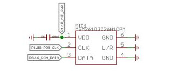
A GPIO is being used to enable the pin power. I've highlighted the relevant part of the Xiao nRF52840 schematic below:
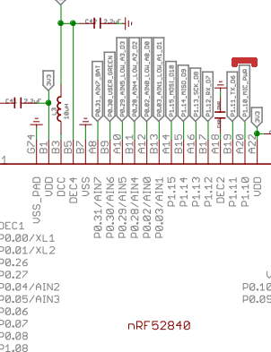
From this schematic highlight you can see GPIO1 10 is the enable pin for the mic.
Bluetooth
To test this setup we can use an existing sample with Zephyr:
west build -p always -b xiao_ble samples/bluetooth/observer
Flash your board:
west flash -r uf2
Wait a moment for the MCU to reset after flashing and connect to monitor:
screen /dev/ttyACM0 115200
You will see a console available for sending commands to the board:
*** Booting Zephyr OS build v3.6.0-5403-gd9e2b0c70763 ***
Starting Observer Demo
Started scanning...
Exiting main thread.
Device found: EC:11:27:22:AF:D2 (public) (RSSI -74), type 0, AD data len 31
Device found: 0D:9A:BE:8D:10:FC (random) (RSSI -81), type 3, AD data len 31
Device found: D2:70:D8:F2:6F:C4 (random) (RSSI -68), type 0, AD data len 20
Device found: 72:7C:3C:87:E2:17 (random) (RSSI -77), type 0, AD data len 17
Device found: 65:65:23:B9:AD:EC (random) (RSSI -68), type 0, AD data len 17
Device found: 6D:39:26:C2:94:B5 (random) (RSSI -70), type 0, AD data len 18
CONFIG_BT=y
CONFIG_BT_OBSERVER=y
The conf file here enables bluetooth related features for the Zephyr build.
TFLite - Hello World
Enable TFLite with Zephyr and update:
west config manifest.project-filter -- +tflite-micro
west update
Build the sample and flash to your board:
west build -p always -b xiao_ble samples/modules/tflite-micro/hello_world
Flash your board:
west flash -r uf2
Wait a moment for the MCU to reset after flashing and connect to monitor:
screen /dev/ttyACM0 115200
You will see results returned from the console:
*** Booting Zephyr OS build v3.6.0-5403-gd9e2b0c70763 ***
x_value: 1.0*2^-127, y_value: 1.0*2^-127

x_value: 1.2566366*2^-2, y_value: 1.4910772*2^-2

x_value: 1.2566366*2^-1, y_value: 1.1183078*2^-1

x_value: 1.8849551*2^-1, y_value: 1.677462*2^-1

x_value: 1.2566366*2^0, y_value: 1.9316229*2^-1

x_value: 1.5707957*2^0, y_value: 1.0420598*2^0

x_value: 1.8849551*2^0, y_value: 1.9146791*2^-1

x_value: 1.0995567*2^1, y_value: 1.6435742*2^-1

x_value: 1.2566366*2^1, y_value: 1.0674761*2^-1

x_value: 1.4137159*2^1, y_value: 1.8977352*2^-3
Additional information about TFLite is outside of the scope of this guide but the example serves as a guide to the capabilities of the device and the components required for running the TFLite setup.
Additional Components
- Grove - Expansion Board - I2C Display
- Grove - Expansion Board - Button
- Grove - Expansion Board - Buzzer
- Grove - Expansion Board - SD Card
- Grove - Temperature and Humidity Sensor (SHT31)
- 1.69inch LCD Display Module, 240×280 Resolution, SPI Interface
- Round Display for Xiao
- Round Display for Xiao - SD Card
Grove - Expansion Board - I2C Display
To test this setup we can use an existing sample with Zephyr:
west build -p always -b xiao_ble samples/drivers/display --  -DSHIELD=seeed_xiao_expansion_board
west flash -r uf2
You'll see a display showing multiple black boxes and a blinking box in the corner given this display only supports two colors.
Let's dive into this example a bit to see why it works:
/ {
    chosen {
      zephyr,display = &ssd1306;
    };
};

&xiao_i2c {
  status = "okay";

  ssd1306: ssd1306@3c {
    compatible = "solomon,ssd1306fb";
    reg = <0x3c>;
    width = <128>;
    height = <64>;
    segment-offset = <0>;
    page-offset = <0>;
    display-offset = <0>;
    multiplex-ratio = <63>;
    segment-remap;
    com-invdir;
    prechargep = <0x22>;
  };
};
The shield sets up a SSD1306 OLED screen at the 0x3C register. It is selected as the zephyr display in the chosen section.
Grove - Expansion Board - Button
To test this setup we can use an existing sample with Zephyr:
west build -p always -b xiao_ble samples/basic/button -- -DSHIELD=seeed_xiao_expansion_board
Flash your board:
west flash -r uf2
Wait a moment for the MCU to reset after flashing and connect to monitor:
screen /dev/ttyACM0 115200
Pressing the button with the sample will trigger the onboard LED to light up.
You will see results returned from the console:
*** Booting Zephyr OS build v3.6.0-5403-gd9e2b0c70763 ***
Set up button at gpio@50000000 pin 3
Set up LED at gpio@50000000 pin 26
Press the button
Button pressed at 839637
Button pressed at 857904
Button pressed at 883367
Button pressed at 1001258
Let's dive into this example a bit to see why it works:
/ {
    aliases {
      sw0 = &xiao_button0;
    };

    buttons {
      compatible = "gpio-keys";
      xiao_button0: button_0 {
        gpios = <&xiao_d 1 (GPIO_PULL_UP | GPIO_ACTIVE_LOW)>;
        label = "SW0";
        zephyr,code = <INPUT_KEY_0>;
      };
    };
};
The shield / overlay file is used to setup various board components. Using this file the button example can be utilized as the overlay allows the Zephyr to configure the button and make it available for the associated code.
In this case D1 on the Xiao nrf52840. It is setup in this overlay to act as a button and is aliased to the sw0 name to allow it to be used for the sample which has code expecting this.
Grove - Expansion Board - Buzzer
We'll activate our buzzer using the blinky PWM example to control its activation via a PWM signal. For this we'll use a custom overlay which enables the PWM for the A3 pin.
cd ~/zephyrproject/zephyr
west build -p always -b xiao_ble samples/basic/blinky_pwm -- -DDTC_OVERLAY_FILE="$(dirname $(pwd))/applications/xiao-zephyr-examples/xiao-nrf52480/xiao_expansion_buzzer.overlay"
After flashing you should begin hearing a series of buzzes which change in sound as the sample runs its course.
Let's look at why this works:
&pwm0 {
 status = "disabled";
};

&sw_pwm {
 status = "okay";
 channel-gpios = <&gpio0 29 PWM_POLARITY_INVERTED>;
};

&pwm_led0 {
 pwms = <&sw_pwm 0 PWM_MSEC(20) PWM_POLARITY_INVERTED>;
};
The overlay configures the PWM logic for the pin 29 which corresponds with the A3 pin from the Xiao nrf52840 pinout.
Grove - Expansion Board - SD Card
We'll use the filesystem sample here along with the Xiao Expansion Board shield to try interfacing with the SD card reader over SPI. The expansion board shield has the CS pin configured for the associated &xiao_d 2 pin so no work is needed on your part for associating this capability with the board aside from adding the shield. To further prepare it we are using a custom config that enables the SD card functionality.
cd ~/zephyrproject/zephyr
west build -p always -b xiao_ble samples/subsys/fs/fs_sample -- -DEXTRA_CONF_FILE="$(dirname $(pwd))/applications/xiao-zephyr-examples/xiao_expansion_sd.conf" -DSHIELD=seeed_xiao_expansion_board
Now flash and monitor (first pressing RESET twice to enter uf2 bootloader mode):
west flash -r uf2
You should see a response similar to this:
*** Booting Zephyr OS build v3.6.0-5403-gd9e2b0c70763 ***
[00:00:00.483,367] <inf> sd: Maximum SD clock is under 25MHz, using clock of 24000000Hz
[00:00:00.483,856] <inf> main: Block count 15519744
Sector size 512
Memory Size(MB) 7578
Disk mounted.

Listing dir /SD: ...
[FILE] IMAGE1.JPG (size = 58422)
[FILE] IMAGE2.JPG (size = 97963)
In this case my SD card had two files. Their names and their sizes were outputted to my console.
Let's look over the relevant elements at play here:
CONFIG_SPI=y
CONFIG_DISK_DRIVER_SDMMC=y
CONFIG_GPIO=y
In the associated config we're enabling SPI, the SDMMC disk driver, and the GPIO. Without this config the overlay will lead to an error as the sample is unable to find the SD card.
The relevant part of the Xiao Expansion Board shield is shown below:
&xiao_spi {
 status = "okay";
 cs-gpios = <&xiao_d 2 GPIO_ACTIVE_LOW>;

 sdhc0: sdhc@0 {
  compatible = "zephyr,sdhc-spi-slot";
  reg = <0>;
  status = "okay";
  mmc {
   compatible = "zephyr,sdmmc-disk";
   status = "okay";
  };
  spi-max-frequency = <24000000>;
 };
};
As mentioned previously the &xiao_d 2 pin mapping is used to allow the D2 pin to be selected for this regardless of the board used so long as it supports the &xiao_d pin setup.
Grove - Temperature and Humidity Sensor (SHT31)
First solder on pins and connect your Xiao nrf52840 to the expansion board. Then connect a grove connector cable between the Grove SHT31 and one of the I2C ports on the expansion board.
To test this setup we can use an existing sample with Zephyr:
west build -p always -b xiao_ble samples/sensor/sht3xd -- -DDTC_OVERLAY_FILE=$(dirname $(pwd))/applications/xiao-zephyr-examples/sht31.overlay
Flash your board after its in uf2 bootloader mode:
west flash -r uf2
Wait a moment for the MCU to reset after flashing and connect to monitor:
screen /dev/ttyACM0 115200
You will see results returned from the console:
*** Booting Zephyr OS build v3.6.0-5403-gd9e2b0c70763 ***
SHT3XD: 25.68 Cel ; 54.73 %RH
SHT3XD: 25.75 Cel ; 55.44 %RH
SHT3XD: 25.79 Cel ; 55.95 %RH
SHT3XD: 25.82 Cel ; 55.93 %RH
SHT3XD: 25.84 Cel ; 56.07 %RH
SHT3XD: 25.84 Cel ; 55.69 %RH
Let's dive into this example a bit to see why it works:
 &xiao_i2c {
 sht3xd@44 {
   compatible = "sensirion,sht3xd";
   reg = <0x44>;
  };
 };
The app overlay file is used to setup various board components. Using this file the SHT31 example can be utilized as the overlay informs the sample logic how to configure the sensor for our board.
1.69inch LCD Display Module, 240×280 Resolution, SPI Interface
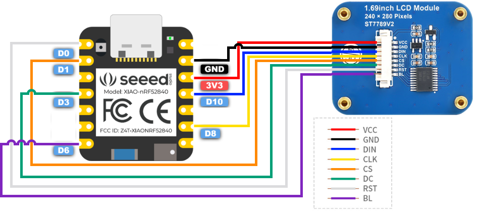
For this example we'll use SPI to connect to a 1.69 inch LCD with a 240x280 resolution.
First connect your board to the LCD screen using the following image as a guide (in this case we're using the Xiao nrf52840 but the same pin layout is used for connecting here).
| 1.69-inch LCD SPI Display | XIAO nrf52840 |
|---|---|
| VCC | 3V3 |
| GND | GND |
| DIN | D10 |
| CLK | D8 |
| CS | D1 |
| DC | D3 |
| RST | D0 |
| BL | D6 |
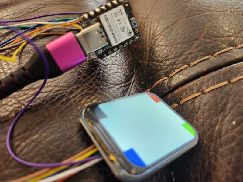
We can now build and flash the firmware:
cd ~/zephyrproject/zephyr
west build -p always -b xiao_ble samples/drivers/display -- -DDTC_OVERLAY_FILE=$(dirname $(pwd))/applications/xiao-zephyr-examples/240x280_st7789v2.overlay -DEXTRA_CONF_FILE=$(dirname $(pwd))/applications/xiao-zephyr-examples/240x280_st7789v2.conf
west flash -r uf2
With the new firmware in place the device now shows the same demo screen we saw previously on the expansion board just now updated for the color LCD over SPI.
Round Display for Xiao
To test this setup we can use an existing sample with Zephyr:
west build -p always -b xiao_ble samples/drivers/display -- -DSHIELD=seeed_xiao_round_display
Enter bootloader mode and flash your device:
west flash -r uf2
You'll see a display showing multiple colored corners with a black corner blinking.
Another example demonstrates the use of the touchscreen:
west build -p always -b xiao_ble samples/modules/lvgl/demos -- -DSHIELD=seeed_xiao_round_display -DCONFIG_LV_Z_DEMO_MUSIC=y
The music demo shown here is only a portion of the actual screen but still demonstrates the touch screen in action. As you can see touching the play button turns on the music animation.
You can see from the shield file that this works by intefacing with the GC9A01 round display driver over SPI and the CHSC6X touch module over i2c.
Let's dive into this example a bit to see how it works:
/ {
    chosen {
      zephyr,display = &gc9a01_xiao_round_display;
    };

 lvgl_pointer {
  compatible = "zephyr,lvgl-pointer-input";
  input = <&chsc6x_xiao_round_display>;
 };
};

/*
 * xiao_serial uses pins D6 and D7 of the Xiao, which are used respectively to
 * control the screen backlight and as touch controller interrupt.
 */
&xiao_serial {
 status = "disabled";
};

&xiao_i2c {
 clock-frequency = < I2C_BITRATE_FAST >;

 chsc6x_xiao_round_display: chsc6x@2e {
  status = "okay";
  compatible = "chipsemi,chsc6x";
  reg = <0x2e>;
  irq-gpios = <&xiao_d 7 GPIO_ACTIVE_LOW>;
 };
};

&xiao_spi {
 status = "okay";
 cs-gpios = <&xiao_d 1 GPIO_ACTIVE_LOW>, <&xiao_d 2 GPIO_ACTIVE_LOW>;

 gc9a01_xiao_round_display: gc9a01@0 {
  status = "okay";
  compatible = "galaxycore,gc9x01x";
  reg = <0>;
  spi-max-frequency = <DT_FREQ_M(100)>;
  cmd-data-gpios = <&xiao_d 3 GPIO_ACTIVE_HIGH>;
  pixel-format = <PANEL_PIXEL_FORMAT_RGB_565>;
  width = <240>;
  height = <240>;
  display-inversion;
 };
};
This shield does the following:
- Selects the GC9A01 display as the chosen Zephyr display
- Sets the LVGL pointer logic to use the CHSC6X module
- Disable serial as the pins are used for backlight and touch interrupt (as seen above via:
irq-gpios = <&xiao_d 7 GPIO_ACTIVE_LOW>;) - Configures the round display for SPI using the D1, D2, and D3 pins
The sample logic relies on the LVGL demo example code which can be further examined.
Round Display for Xiao - SD Card
We'll use the filesystem sample here along with the Xiao Expansion Board shield to try interfacing with the SD card reader over SPI. The expansion board shield has the CS pin configured for the associated &xiao_d 2 pin so no work is needed on your part for associating this capability with the board aside from adding the shield. To further prepare it we are using a custom config that enables the SD card functionality.
cd ~/zephyrproject/zephyr
west build -p always -b xiao_ble samples/subsys/fs/fs_sample -- -DEXTRA_CONF_FILE="$(dirname $(pwd))/applications/xiao-zephyr-examples/xiao_expansion_sd.conf" -DSHIELD=seeed_xiao_round_display
Now flash and monitor (first pressing RESET twice to enter uf2 bootloader mode):
west flash -r uf2
Wait a moment for the MCU to reset after flashing and connect to monitor:
screen /dev/ttyACM0 115200
You should see a response similar to this:
*** Booting Zephyr OS build v3.6.0-5403-gd9e2b0c70763 ***
[00:00:00.491,485] <inf> sd: Maximum SD clock is under 25MHz, using clock of 24000000Hz
[00:00:00.491,973] <inf> main: Block count 15519744
Sector size 512
Memory Size(MB) 7578
Disk mounted.

Listing dir /SD: ...
[FILE] IMAGE1.JPG (size = 58422)
[FILE] IMAGE2.JPG (size = 97963)
As expected the file contents are displayed in a similar manner to the output from the Xiao Expansion board SD card example.
The relevant part of the round display shield is shown below:
&xiao_spi {
 status = "okay";
 cs-gpios = <&xiao_d 1 GPIO_ACTIVE_LOW>, <&xiao_d 2 GPIO_ACTIVE_LOW>;

 sdhc_xiao_round_display: sdhc@1 {
  compatible = "zephyr,sdhc-spi-slot";
  reg = <1>;
  status = "okay";
  mmc {
   compatible = "zephyr,sdmmc-disk";
   status = "okay";
  };
  spi-max-frequency = <DT_FREQ_M(24)>;
 };
};
D2 is used for the SD CS pin.
✨ Contributor Project
- This project is supported by the Seeed Studio Contributor Project.
- Thanks Tim's efforts and your work will be exhibited.
Tech Support & Product Discussion
Thank you for choosing our products! We are here to provide you with different support to ensure that your experience with our products is as smooth as possible. We offer several communication channels to cater to different preferences and needs.