NFC Usage on Seeed Studio XIAO nRF52840 (Sense)
Both the Seeed Studio XIAO nRF52840 series are equipped with an NFC (Near Field Communication) module based on the nRF52840's built-in NFCT (Near Field Communication Tag) peripheral. It supports NFC Type 2 Tag functionality. By connecting an external NFC antenna, the XIAO nRF52840 can act as an NFC tag and be read by smartphones and other NFC readers.
This wiki walks you through the complete NFC usage workflow — from library installation, hardware connection, antenna tuning, to setup verification and creating your own NFC tag.
This tutorial is based on the XIAO_nRF52840_NFC library. The Seeed nRF52 Boards version 1.1.13 has been tested and approved.
Preparatory Work
For the board libraries installation, please refer to this tutorial to finish installing the Seeed nRF52 Boards. If you have already installed, we can move on.
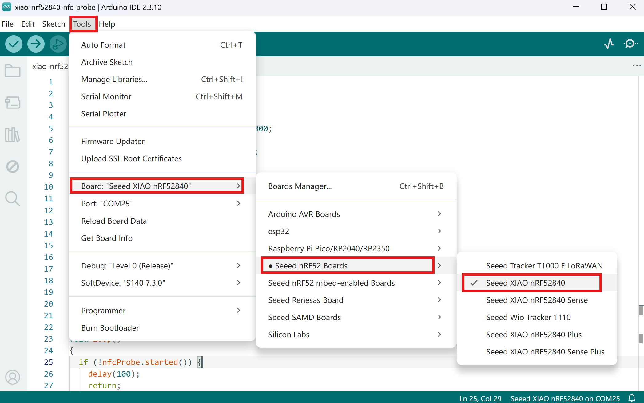
Make sure to select the Seeed XIAO nRF52840 board in the Boards Manager. The older "Seeed nRF52 mbed-enabled Boards" library is no longer maintained and should not be used.
Hardware Required
| Seeed Studio XIAO nRF52840 | Seeed Studio XIAO nRF52840 Plus |
|---|---|
 |  |
| Seeed Studio XIAO nRF52840 Sense | Seeed Studio XIAO nRF52840 Sense Plus |
 |  |
The basic NFC functionality works with just the antenna soldered to NFC1/NFC2. After community testing (special thanks to andriandreo from the Seeed forum), both of the following antennas worked right after soldering without further circuit tuning:
- MOLEX 1462360051
- TAOGLAS FXR.07.A.DG
Later, we added two 43 pF tuning capacitors from each NFC pad (D14, D15) to GND for the TAOGLAS FXR.07.A.DG to further enhance the interrogation distance. The ~40 pF capacitor value was calculated from subsection "6.14.10 NFCT antenna recommendations" in the nRF52840 MCU product specification datasheet.
If you experience unstable behavior (incomplete pop-ups, intermittent detection), adding matching capacitors will significantly improve reliability. See Antenna Tuning for details.
For more real-world testing insights, check out the original forum discussion.
Software Required
| Item | Version / Notes |
|---|---|
| Arduino IDE | 1.8.x or later |
| Seeed nRF52 Boards | 1.1.13 (install via Arduino IDE Boards Manager) |
| XIAO_nRF52840_NFC Library | Download from GitHub, install via Sketch > Include Library > Add .ZIP Library (see below) |
| NFC Tools App | Android / Apple |
Installing the XIAO_nRF52840_NFC Library
This library is not included in the Arduino Library Manager — you need to install it manually from GitHub.
- Step 1. Go to the XIAO_nRF52840_NFC GitHub repository, click the green Code button, and select Download ZIP.
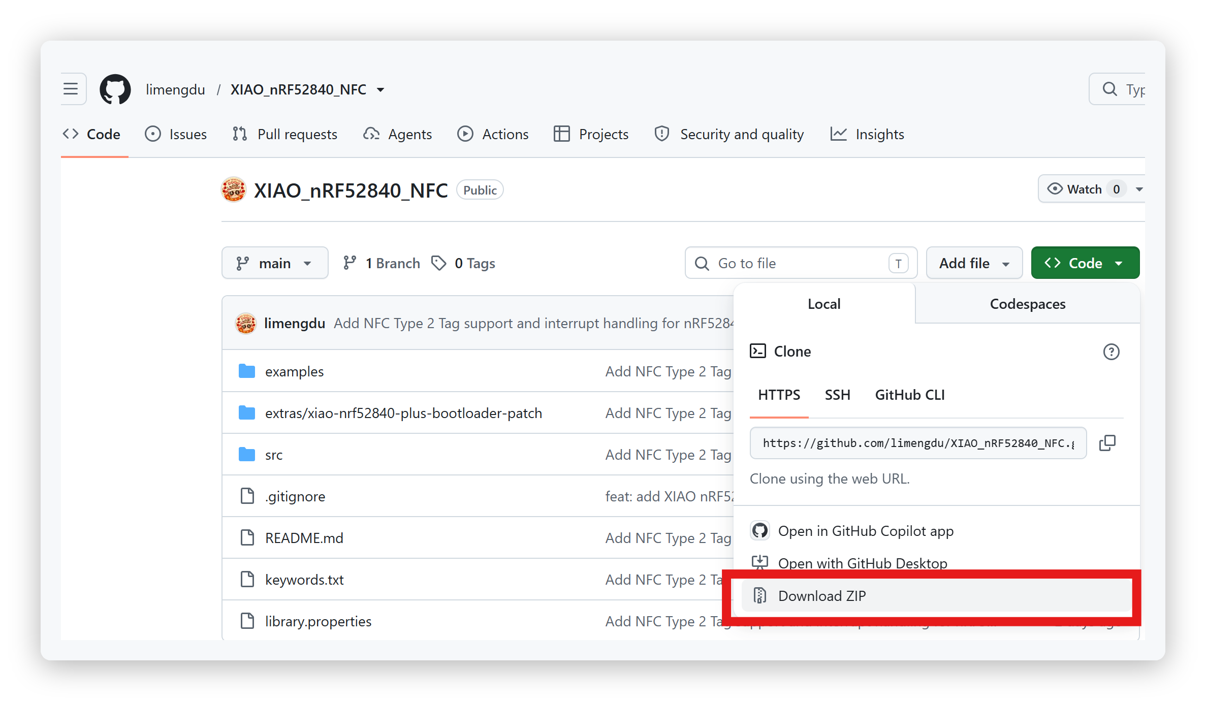
- Step 2. Open Arduino IDE, go to Sketch > Include Library > Add .ZIP Library....
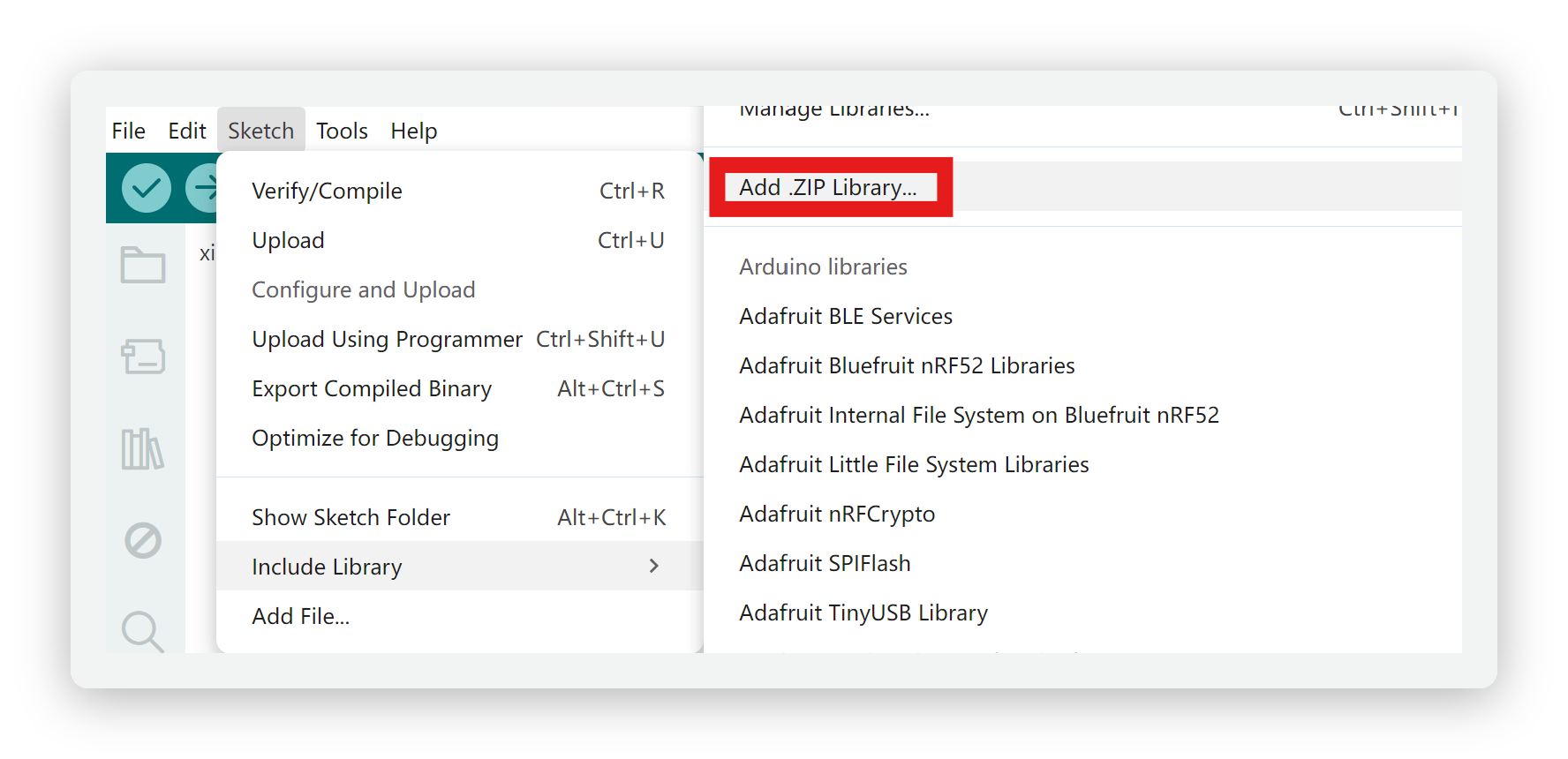
-
Step 3. Select the downloaded ZIP file (
XIAO_nRF52840_NFC-main.zip). You should see "Library added to your libraries" in the status bar. -
Step 4. Restart Arduino IDE. After restarting, you should see the examples under File > Examples > XIAO_nRF52840_NFC.
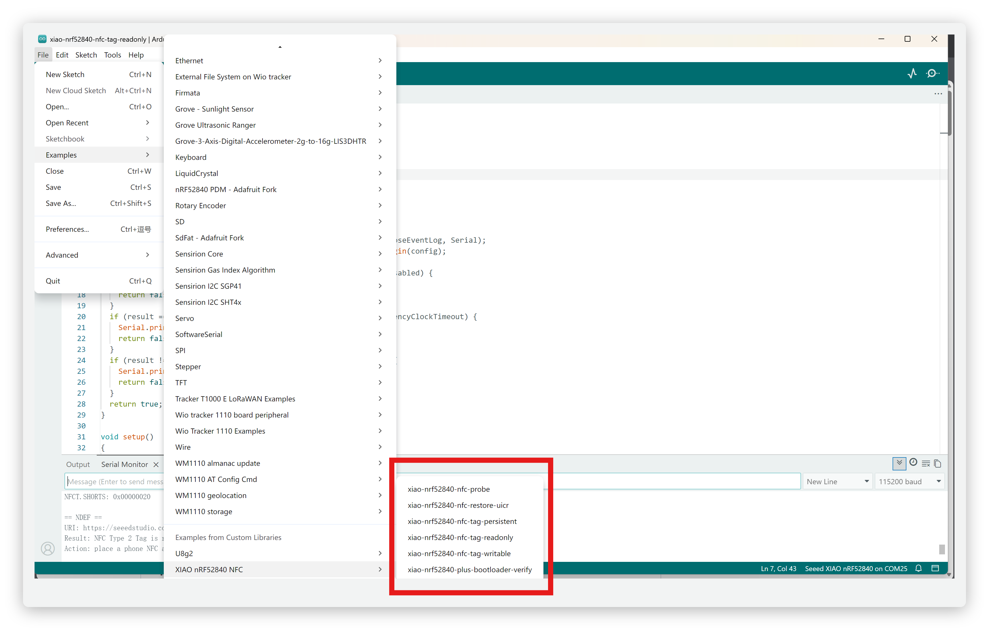
Hardware Connection
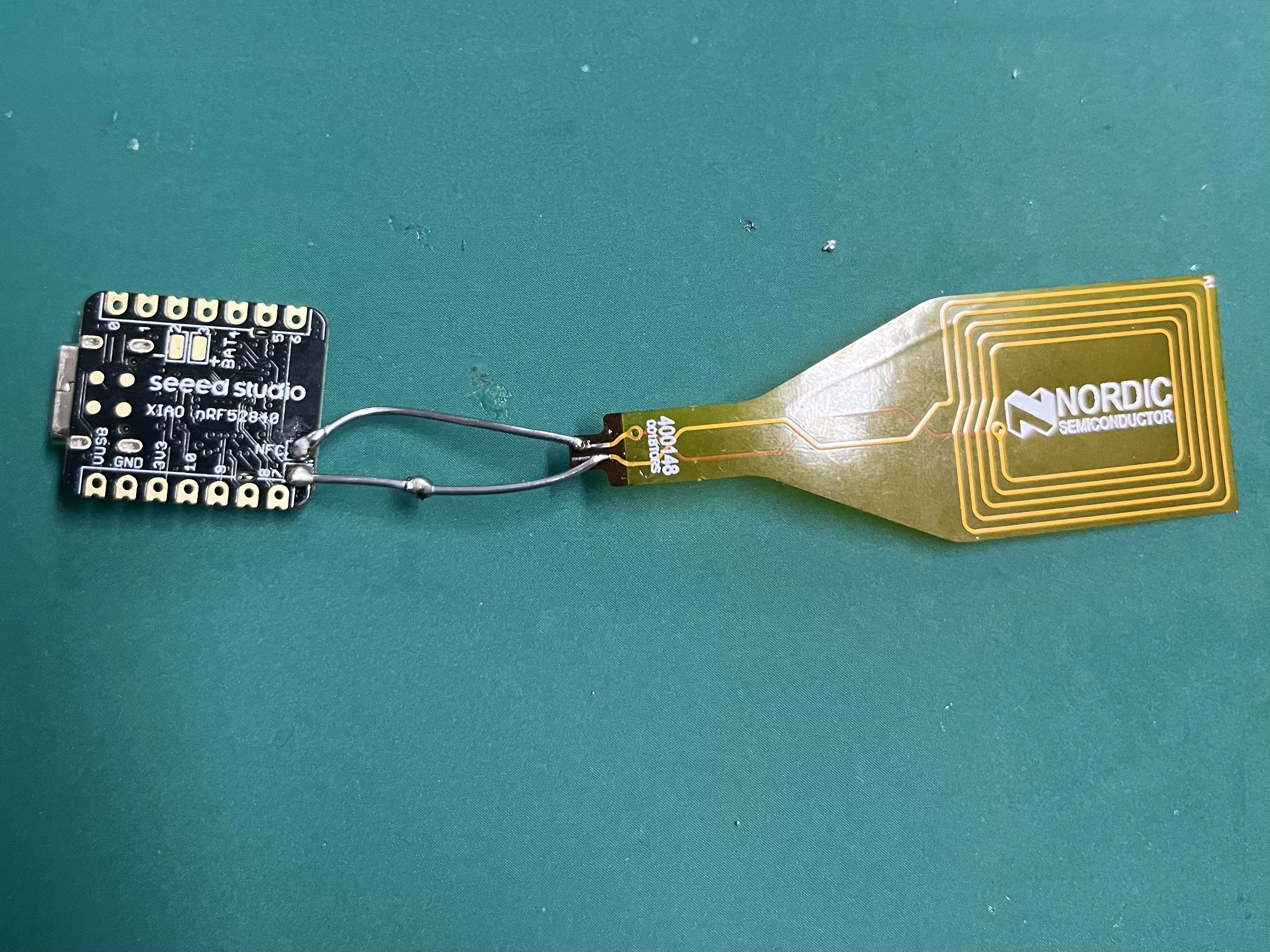
XIAO nRF52840's NFC pins are located on the back of the board, labeled P0.09 and P0.10:
D14 (P0.09) — NFC1 — Antenna end A
D15 (P0.10) — NFC2 — Antenna end B
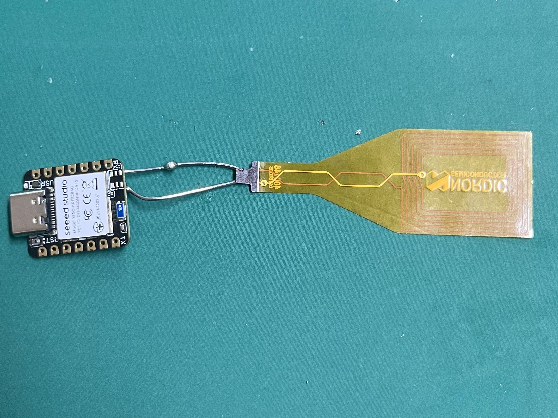
Solder the NFC antenna to P0.09 and P0.10 as shown below:
In this tutorial, we are using the Seeed Studio XIAO nRF52840 with a Nordic-recommended NFC antenna for demonstration.
Front view:
Back view:
- NFC antenna is a differential signal and has no polarity — either end can go to D14 or D15.
- The two pins ship from factory as NFC antenna mode (UICR =
0xFFFFFFFF) on XIAO nRF52840 and XIAO nRF52840 Sense. On XIAO nRF52840 Plus and XIAO nRF52840 Sense Plus, they may be configured as GPIO by default — check UICR first (see Step 1). - It is recommended to measure DC resistance across the antenna terminals with a multimeter before soldering (usually 1–3 Ω) to confirm continuity and rule out shorts.
Antenna Tuning
NFC relies on a resonant LC tank circuit. The antenna coil provides inductance (L), and the matching capacitors provide capacitance (C). Together they form a resonant circuit at the target frequency:
f = 1 / (2π√(LC))
The target is 13.56 MHz. Without external capacitors, only the nRF52840's internal ~4 pF parasitic capacitance participates — the resonance point is far from 13.56 MHz. The NFC function will still work, but communication may be unstable: phone pop-ups may show "NFC tag detected" without the full content, and error codes may appear in the serial output. Adding matching capacitors brings the LC tank to resonance and dramatically improves reliability.
All the operations below are based on the Nordic Official NFC Antenna Design document. The chip delivers full power only when it sees a differential 100 Ω load at resonance.
Fixed Parameters
| Item | Fixed Value | Source |
|---|---|---|
| Operating frequency f | 13.56 MHz | Global NFC standard, hard-coded in nRF52840 |
| Load impedance | 100 Ω (differential) | Nordic white-paper nWP_026 |
Measurements You Need
- Coil inductance L — measure with a DMM / LCR meter / VNA at 100 kHz, value in µH.
- Coil loss resistance R — read the series resistance from the same screen, in Ω.
Step 1: Impedance Pre-Check
Using the impedance-transformation formula:
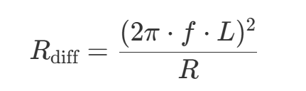
Target: 90–120 Ω, the closer to 100 Ω the better.
| Result | Meaning | Next Step |
|---|---|---|
| < 60 Ω | Antenna too small | Add turns or enlarge the coil area |
| 90 – 120 Ω | PASS | Go to Step 2 |
| > 150 Ω | Antenna too big | Remove turns or shrink the coil area |
Only after this gate is passed do you calculate capacitors; otherwise any capacitor value is useless.
Step 2: Calculate Resonant Capacitance
Formula with fixed 13.56 MHz:
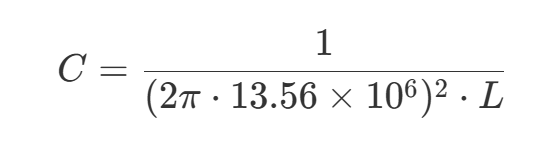
This gives the total capacitance needed. For a π-network, split equally:
C1 = C2 = C / 2
Pick the closest E12 value (e.g., 39 pF, 47 pF, 56 pF, 68 pF …).
Recommended Antenna
If you don't have an LCR meter and prefer a known starting point, a standard 13.56 MHz NFC coil antenna works well with the XIAO nRF52840. Below is the antenna we used during testing:
| Parameter | Value |
|---|---|
| Type | 13.56 MHz NFC coil |
| DC Resistance | ~2.3 Ω |
| Connection | Solder directly to NFC1 / NFC2 |
The antenna shown above is not a Seeed Studio product. You can use any 13.56 MHz NFC coil antenna with similar specifications. The key is to measure the inductance and calculate the matching capacitor value using the formulas above.
NFC Setup & Examples
The following workflow first verifies your NFC hardware setup, then walks you through creating your own NFC tag. We use the XIAO_nRF52840_NFC library, which wraps the nRF52840 NFCT peripheral into a clean Arduino API.
The library includes six example sketches:
| Category | Example Sketch | Purpose |
|---|---|---|
| Verification | xiao-nrf52840-nfc-probe | Check UICR pin configuration + verify RF link |
xiao-nrf52840-nfc-restore-uicr | Restore NFC pins if they were changed to GPIO | |
| Plus Fix | xiao-nrf52840-plus-bootloader-verify | Verify bootloader on Plus variants before UICR restore |
| Demo | xiao-nrf52840-nfc-tag-readonly | Read-Only Tag — phone reads a fixed URL |
xiao-nrf52840-nfc-tag-writable | Writable Tag — phone can write data to the tag | |
xiao-nrf52840-nfc-tag-persistent | Persistent Tag — data survives power cycles (stored in Flash) |
Step 1: Check UICR Pin Configuration
Purpose: Confirm P0.09/P0.10 are configured as NFC antenna pins.
Open File > Examples > XIAO_nRF52840_NFC > xiao-nrf52840-nfc-probe and upload it to your board. (Steps 1 and 2 share the same sketch — one upload does both.)
Open Serial Monitor at 115200 baud. The first few lines show the current UICR status:
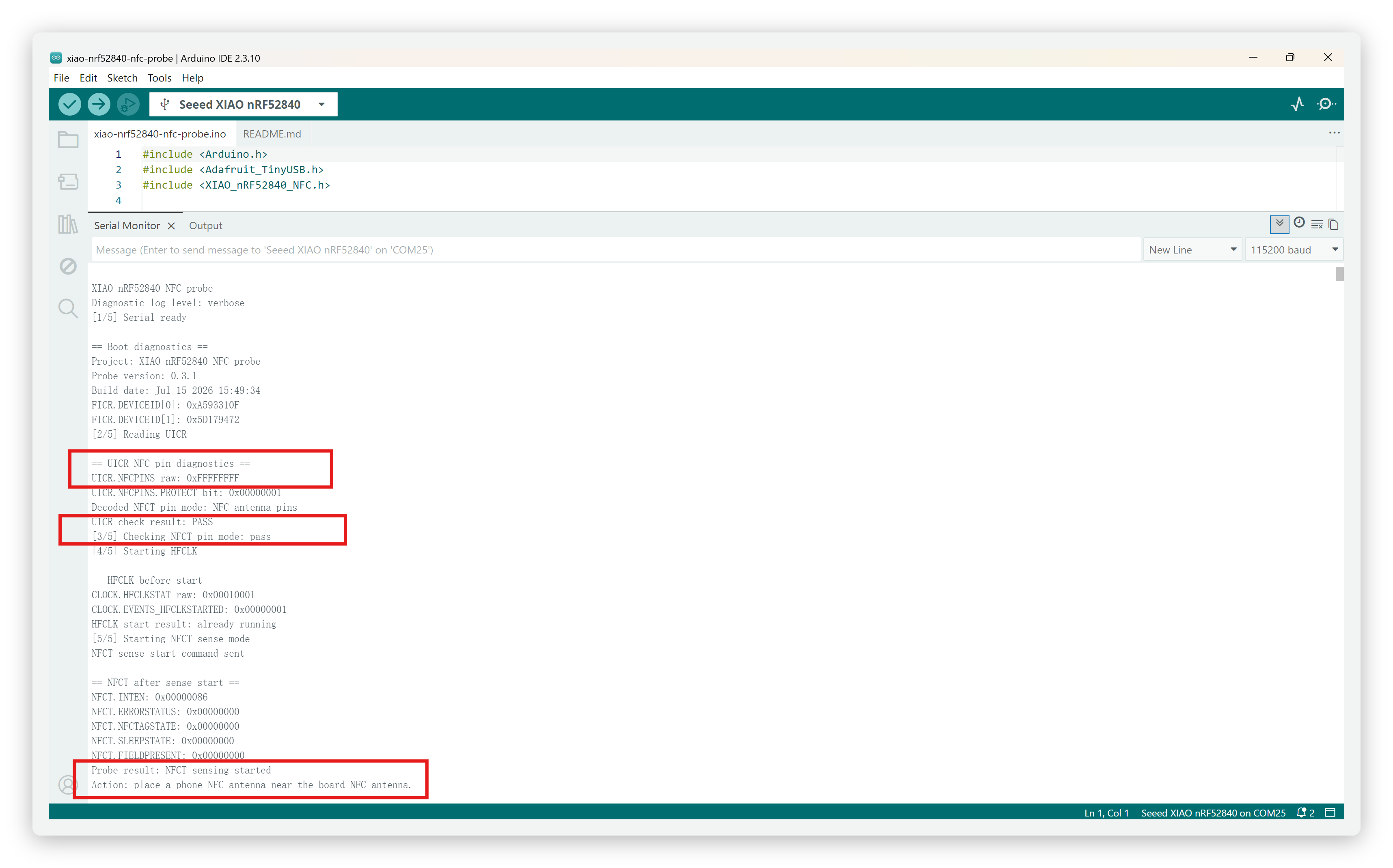
How to interpret the output:
| UICR Value | Meaning | Action |
|---|---|---|
0xFFFFFFFF | NFC antenna mode ✅ | Proceed to Step 2 |
0xFFFFFFFE | GPIO mode ❌ | Upload xiao-nrf52840-plus-bootloader-verify first (Plus variants), then upload xiao-nrf52840-nfc-restore-uicr, send RESTORE_NFC in Serial Monitor, confirm Verify result: PASS, then power-cycle the board |
XIAO nRF52840 and XIAO nRF52840 Sense ship from factory with UICR = 0xFFFFFFFF (NFC mode). In most cases, this step is a pass and no action is needed. XIAO nRF52840 Plus and XIAO nRF52840 Sense Plus may ship with GPIO mode — if the output shows 0xFFFFFFFE, follow the restore action below.
Step 2: Probe — Verify RF Link
Purpose: Confirm that NFC command frames from the phone can reach the board.
After the UICR check, the same sketch automatically enters Probe mode. In this mode, the tag does not reply to any frames — it only listens. This isolates the receive direction, making it easy to confirm whether the RF link is alive.
Place your phone's NFC area close to the antenna for a few seconds, then check the Serial Monitor output:
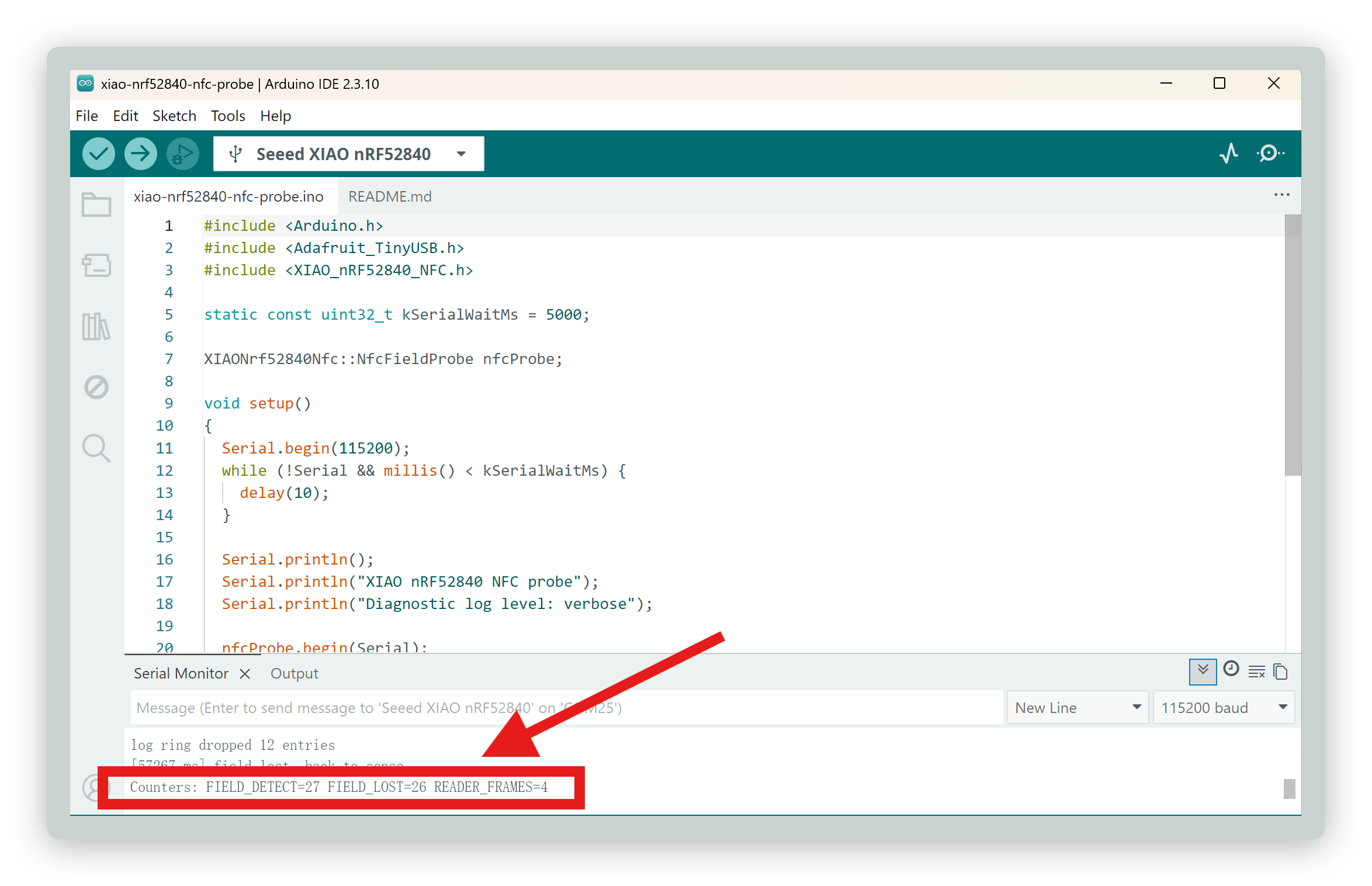
Key indicators:
| Counter | Meaning | Pass Criteria |
|---|---|---|
FIELD_DETECT | Phone's 13.56 MHz RF field detected | > 0 |
FIELD_LOST | RF field disappeared | Close to FIELD_DETECT |
READER_FRAMES | NFC command frames received from phone | > 0 (critical) |
READER_FRAMES > 0means the phone's command frames successfully reached the board and the bidirectional RF link is established. The phone should not show a pop-up at this stage (Probe mode does not reply).
Common error codes:
| Error Code | Name | Meaning |
|---|---|---|
0x01 | FRAMEDELAYTIMEOUT | Frame delay timeout — tag did not receive next command within expected interval |
0x02 | NFCANTENNAERROR | NFCT cannot drive antenna — usually caused by impedance mismatch or missing antenna |
0x80 | RX frame receive error | Frame received but CRC/parity check failed (may appear in Readonly stage) |
Demo 1: Read-Only Tag
Purpose: A simple NFC tag that broadcasts a fixed URL. The phone reads it and displays a pop-up — the most common NFC use case.
Open File > Examples > XIAO_nRF52840_NFC > xiao-nrf52840-nfc-tag-readonly and upload it. Place your phone on the antenna for 2–3 seconds.
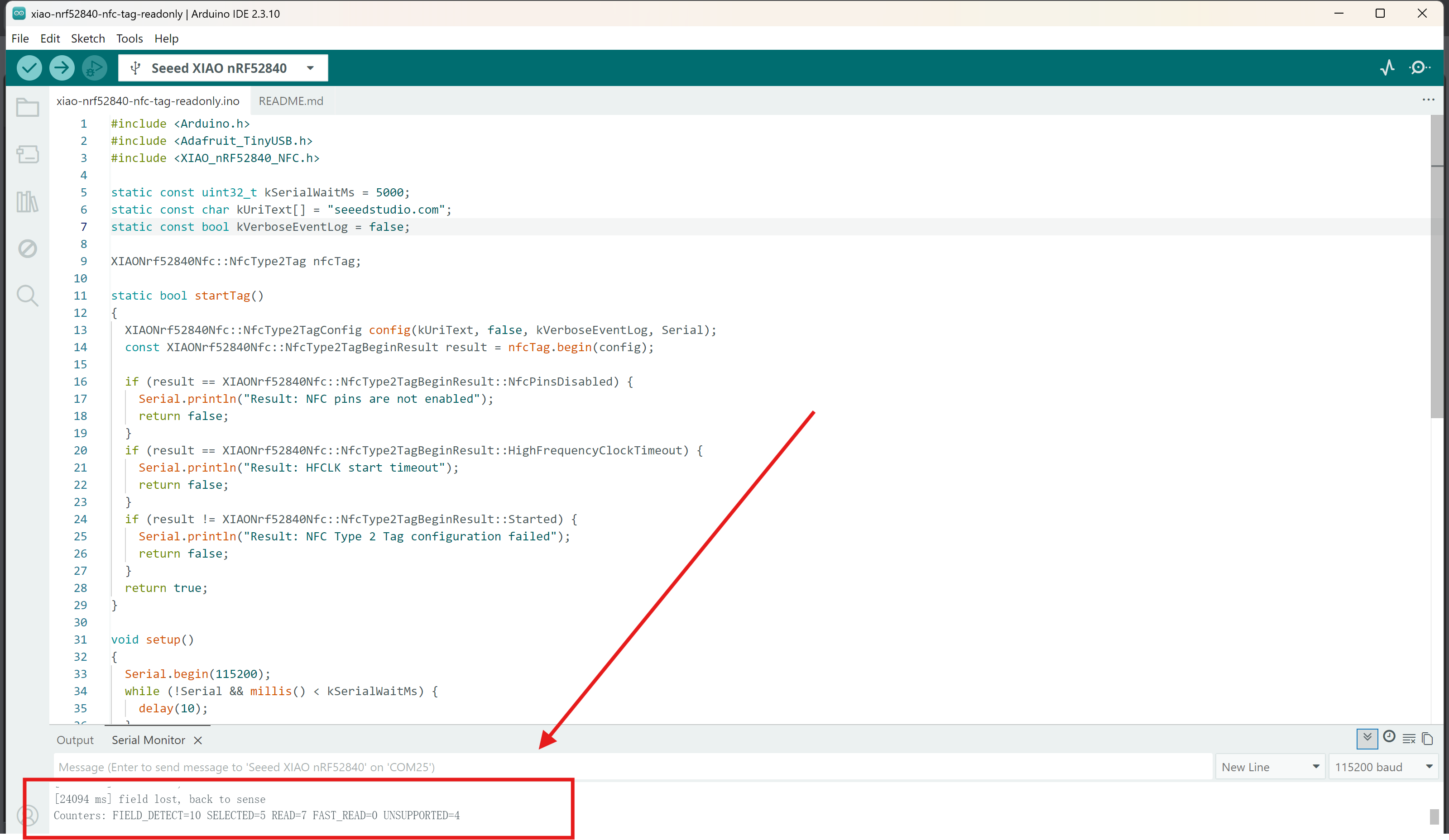
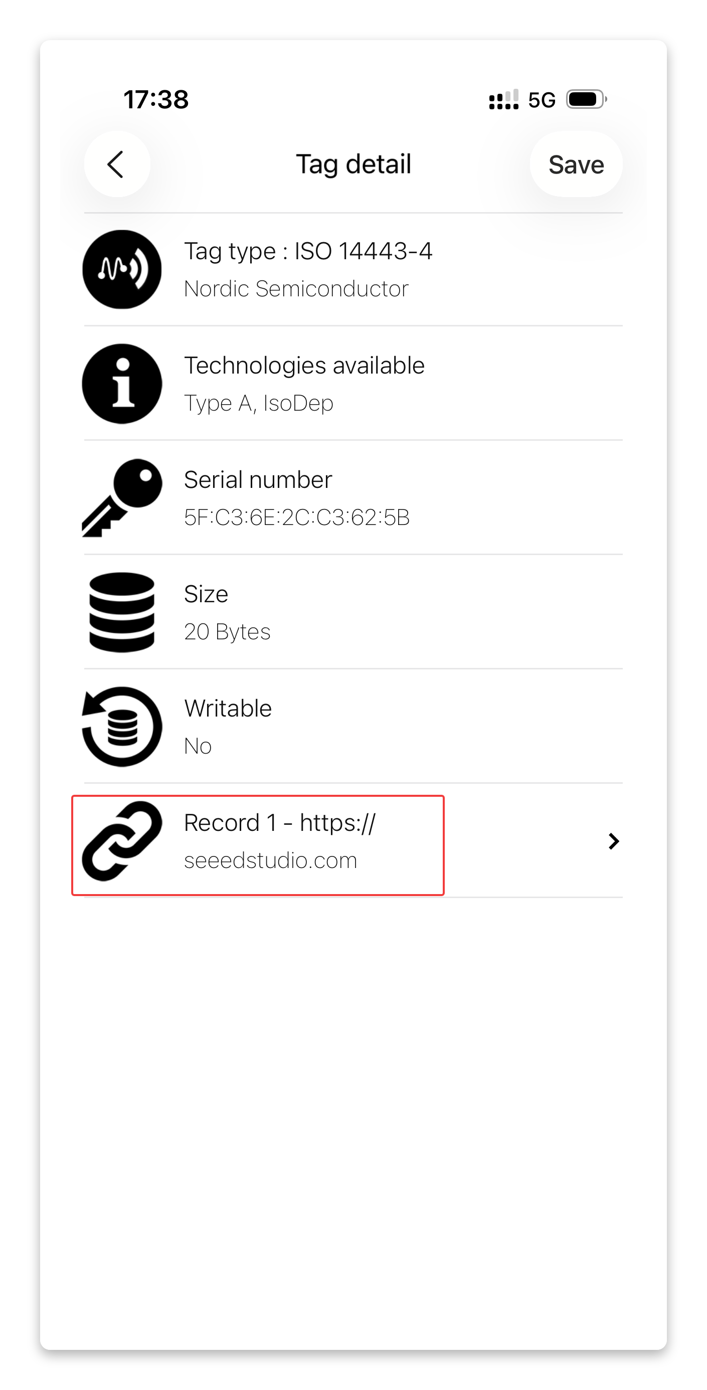
The phone should display a pop-up containing the link https://seeedstudio.com.
Key indicators:
| Counter | Meaning | Pass Criteria |
|---|---|---|
FIELD_DETECT | Phone's 13.56 MHz RF field detected | > 0 |
SELECTED | Phone completed anti-collision + SELECT handshake | > 0 (core indicator) |
READ | Phone successfully read NDEF data pages | > 0 |
FAST_READ | Number of FAST_READ requests received | 0 or small (normal) |
UNSUPPORTED | Phone sent an unsupported command | A few is normal |
SELECTED > 0is the key threshold: the anti-collision flow passed and the phone recognized the Type 2 Tag.READ > 0means NDEF pages were actually read. The final verification is that the phone displays the full URL pop-up.
The URL is hard-coded in the sketch. To change it, open the sketch and modify the NDEF message, then re-upload. The tag data is stored in RAM and will be lost after a power cycle.
Demo 2: Writable Tag
Purpose: An NFC tag that the phone can both read and write. The tag starts with a default URI (https://seeedstudio.com), and the phone can overwrite it with new NDEF content using the NFC Tools app.
Open File > Examples > XIAO_nRF52840_NFC > xiao-nrf52840-nfc-tag-writable and upload it.
Test steps:
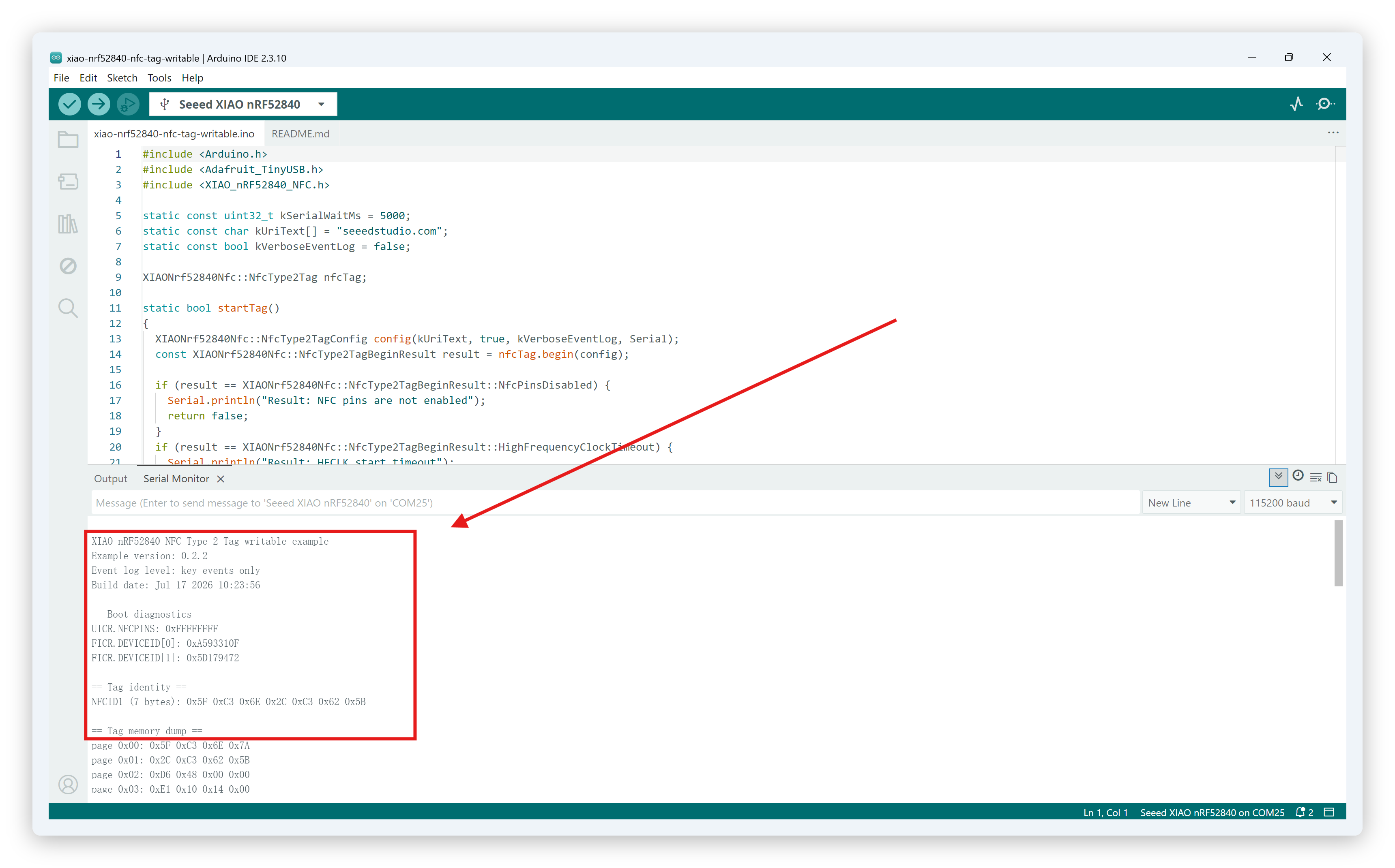
- Step 1. Open Serial Monitor at 115200 baud. The boot log shows the tag identity (NFCID1), initial memory dump, and the default URI (
https://seeedstudio.com).
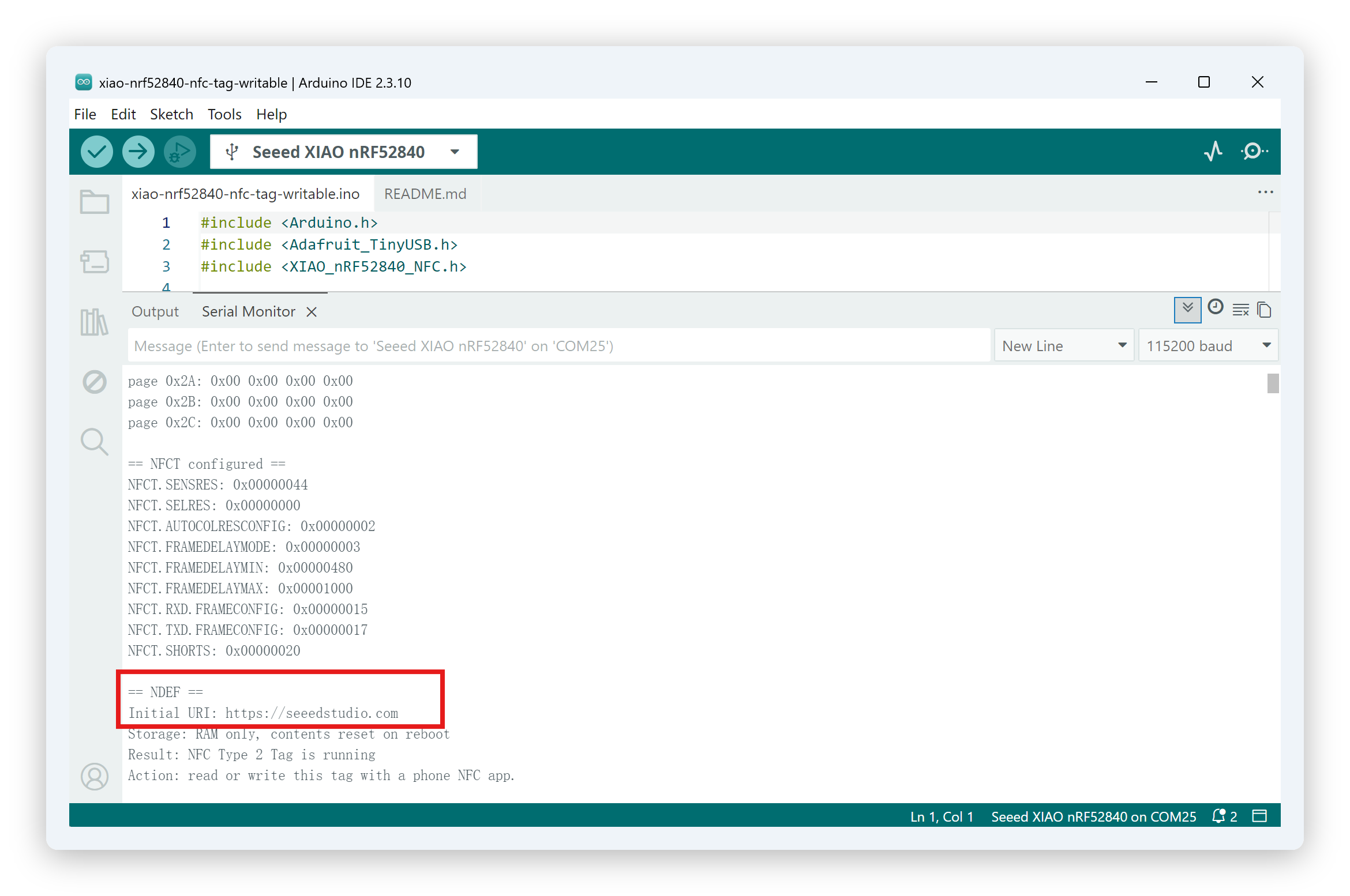
The boot log also prints the default URI that the tag will broadcast:
-
Step 2. Read the tag with your phone first. The phone should detect
https://seeedstudio.com. -
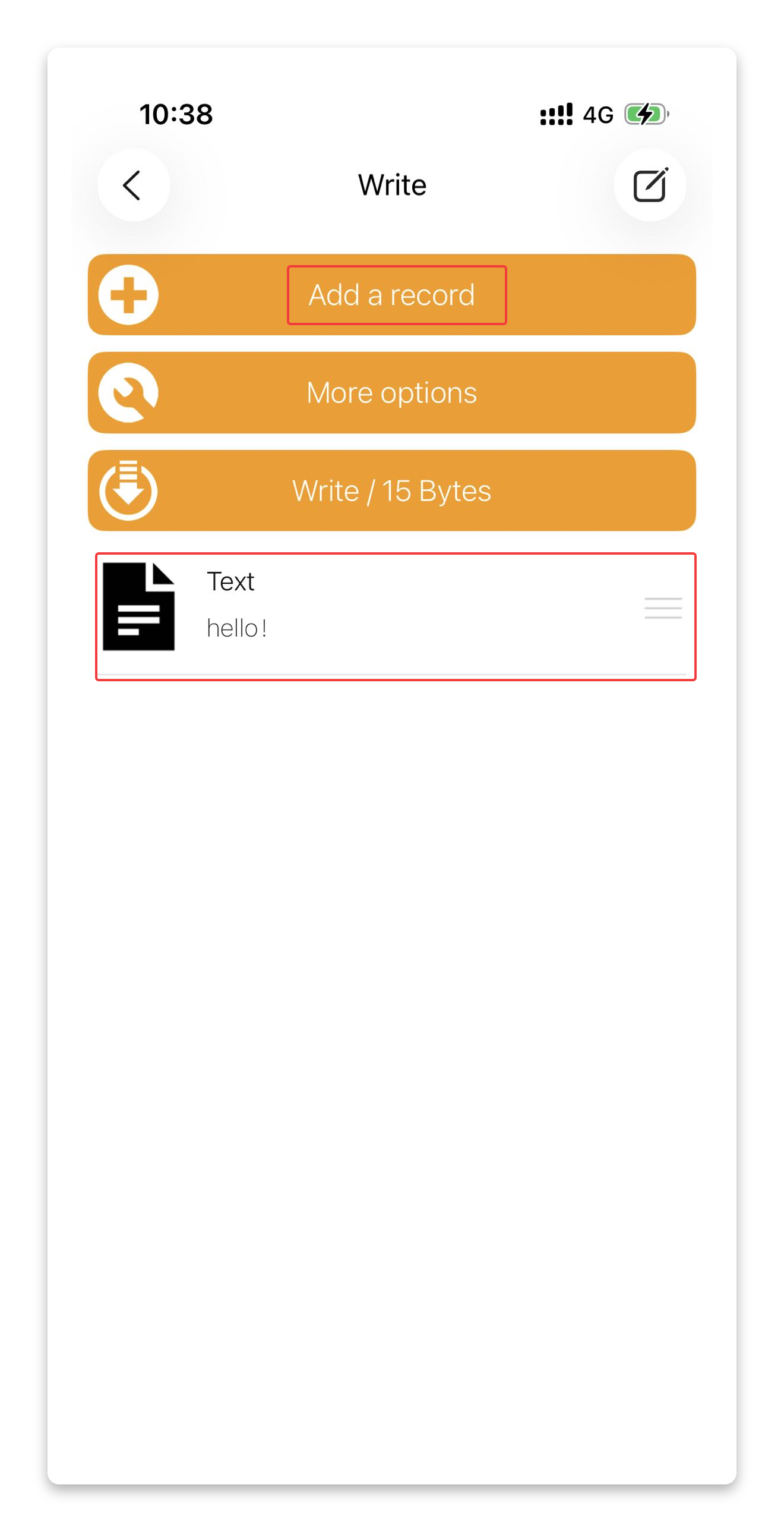
Step 3. Open NFC Tools (or any NFC writer app), write the content you want to the tag. In this example, we write a simple text:
hello!. After entering your content, click "Write / XX Bytes" — the byte count depends on the length of your content.
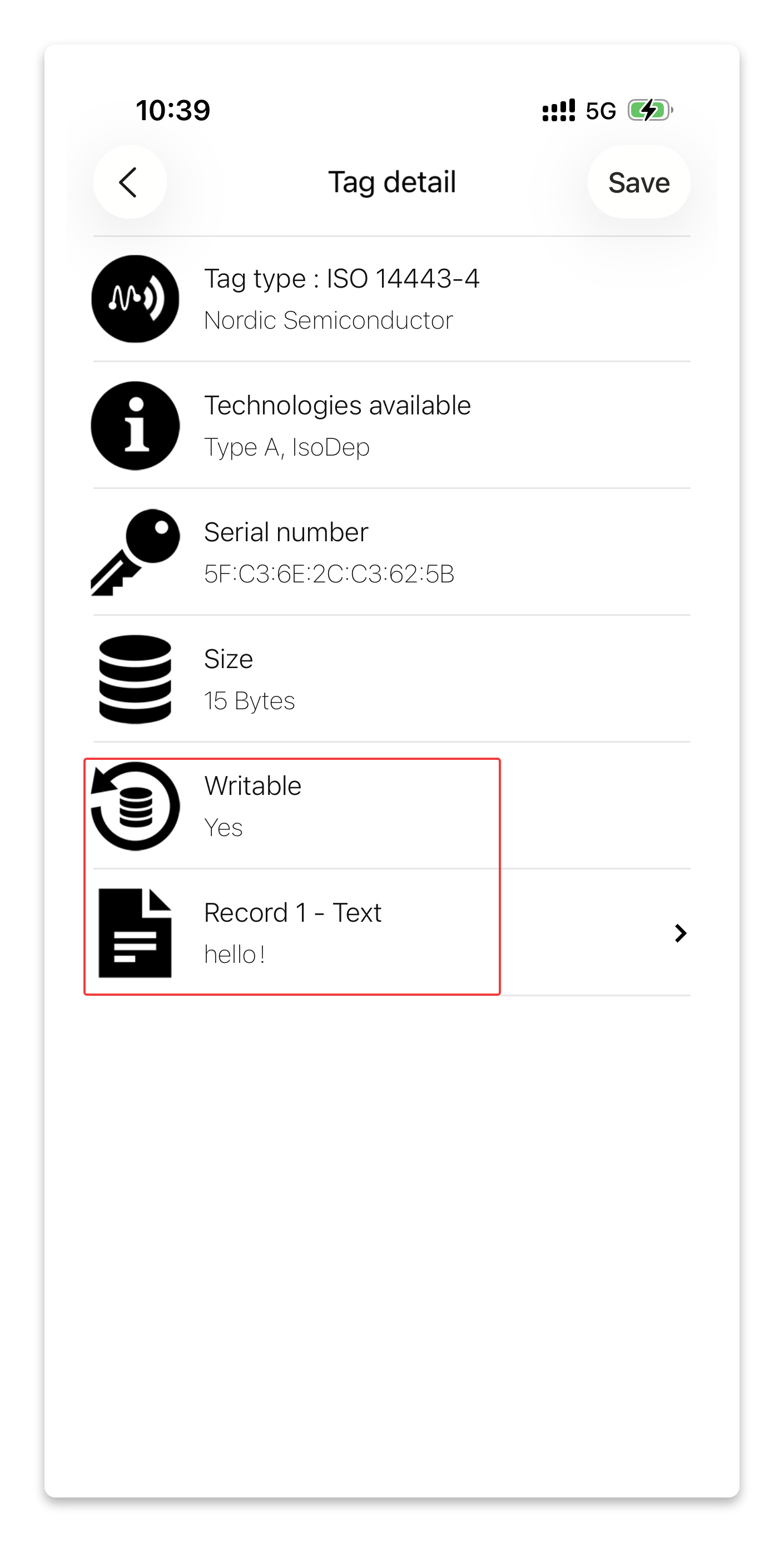
- Step 4. Read the tag again. The phone should now display the newly written content (
hello!).
After the phone leaves the NFC field, the Serial Monitor shows the updated key indicators reflecting the complete read-after-write session:
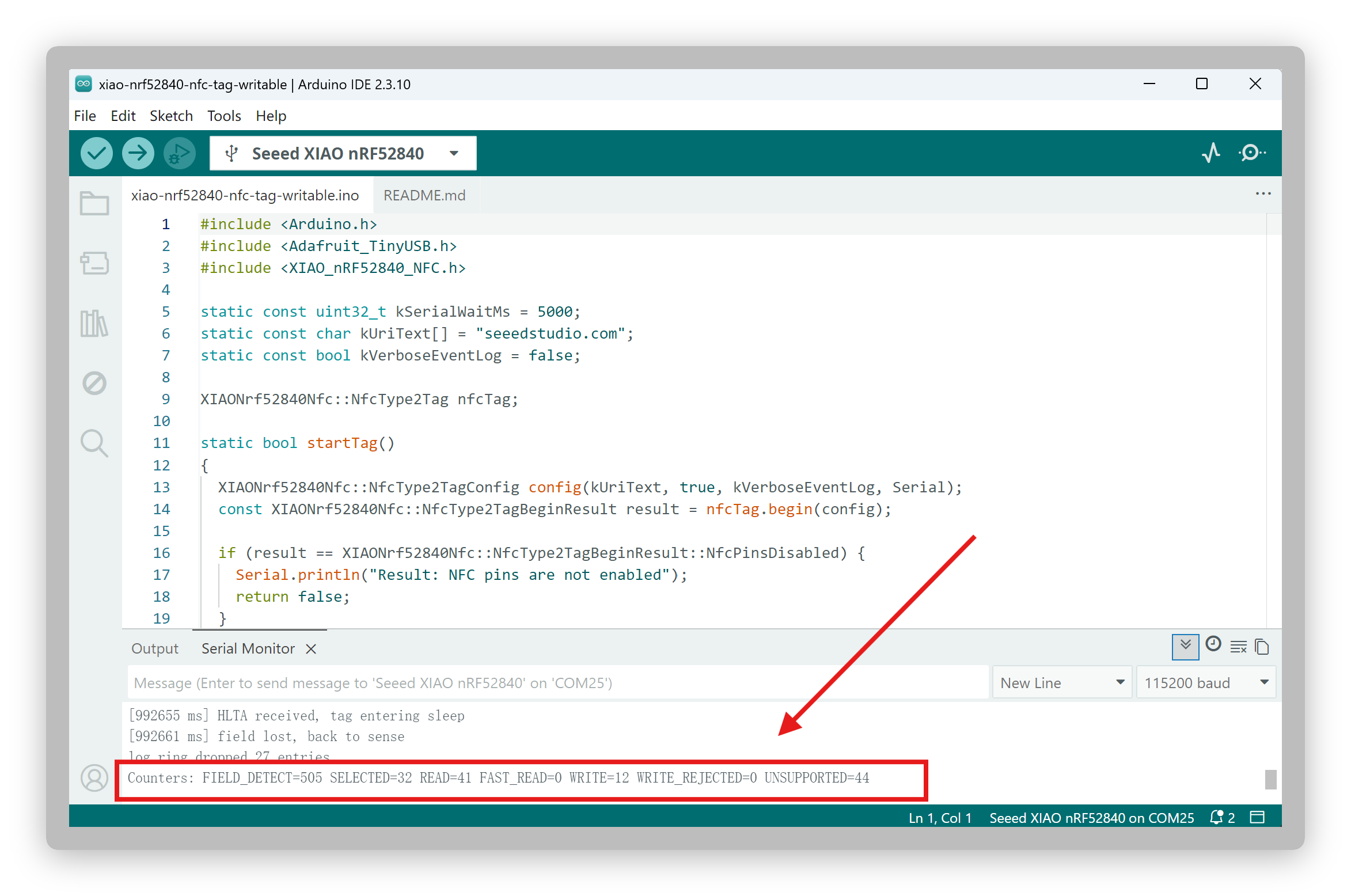
Key indicators:
| Counter | Meaning | Pass Criteria |
|---|---|---|
FIELD_DETECT | Phone's 13.56 MHz RF field detected | > 0 |
SELECTED | Phone completed anti-collision + SELECT handshake | > 0 (core indicator) |
READ | Phone successfully read NDEF data pages | > 0 |
WRITE | Phone successfully wrote data to the tag | > 0 (core indicator) |
FAST_READ | Number of FAST_READ requests received | 0 or small (normal) |
WRITE_REJECTED | Write attempts rejected (protected pages) | 0 (should never occur with standard apps) |
UNSUPPORTED | Phone sent an unsupported command | A few is normal |
WRITE > 0is the key threshold for Writable: the phone successfully wrote data to the tag.WRITE_REJECTEDshould always be0— if it increases, something went wrong during the write session.
The written data is stored in RAM only and will be lost after a power cycle, restoring the default URI — which makes repeated write tests easy. For data that needs to survive power cycles, use the Persistent Tag demo below.
Demo 3: Persistent Tag
Purpose: An NFC tag whose data survives power cycles. The NDEF content is stored in the nRF52840's internal Flash memory (LittleFS), so it persists even after the board is powered off and on again — ideal for long-term deployments.
Open File > Examples > XIAO_nRF52840_NFC > xiao-nrf52840-nfc-tag-persistent and upload it.
Test steps:
- Step 1. On first boot, open Serial Monitor at 115200 baud. The boot log shows the default URI and
Storage state: no stored content, using default URI.
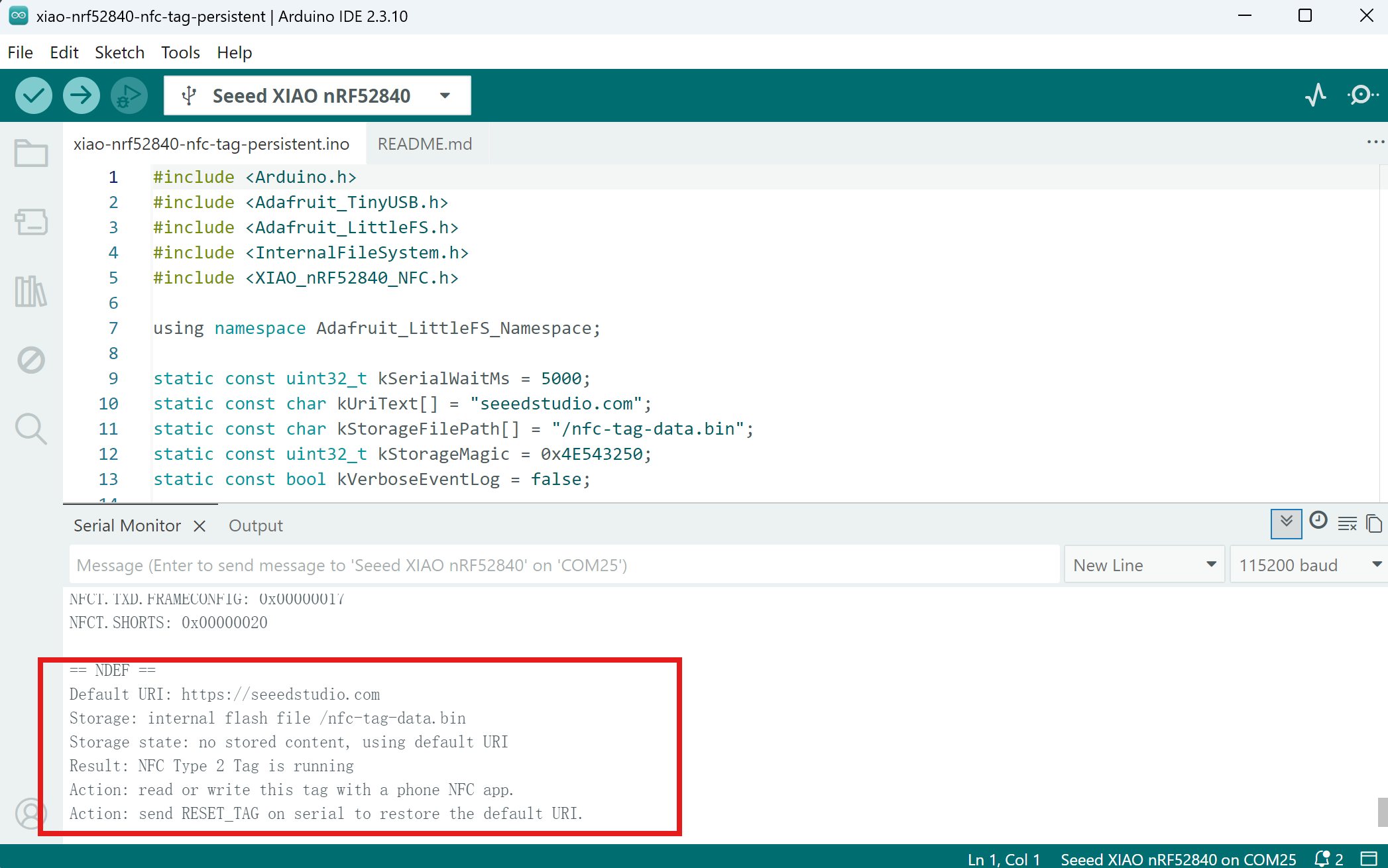
-
Step 2. Read the tag with your phone. On first boot, the phone detects
https://seeedstudio.com. -
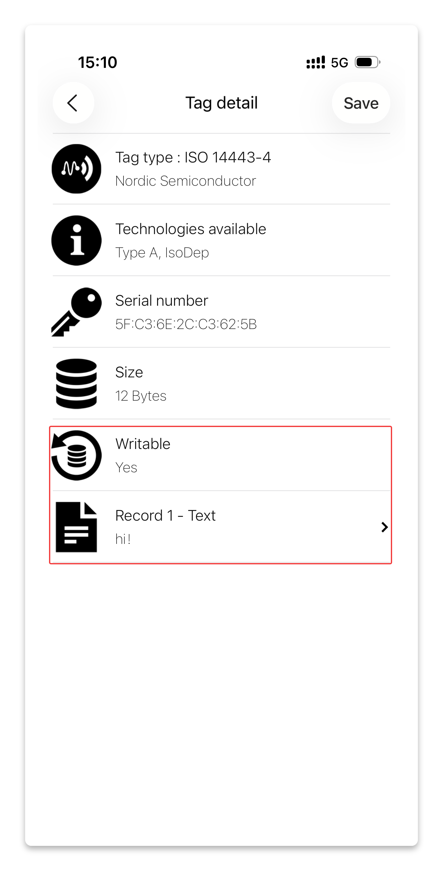
Step 3. Open NFC Tools (or any NFC writer app), write a new text or URL record to the tag. In this example, we write a simple text:
hi!. After entering your content, click "Write / XX Bytes" — the byte count depends on the length of your content.
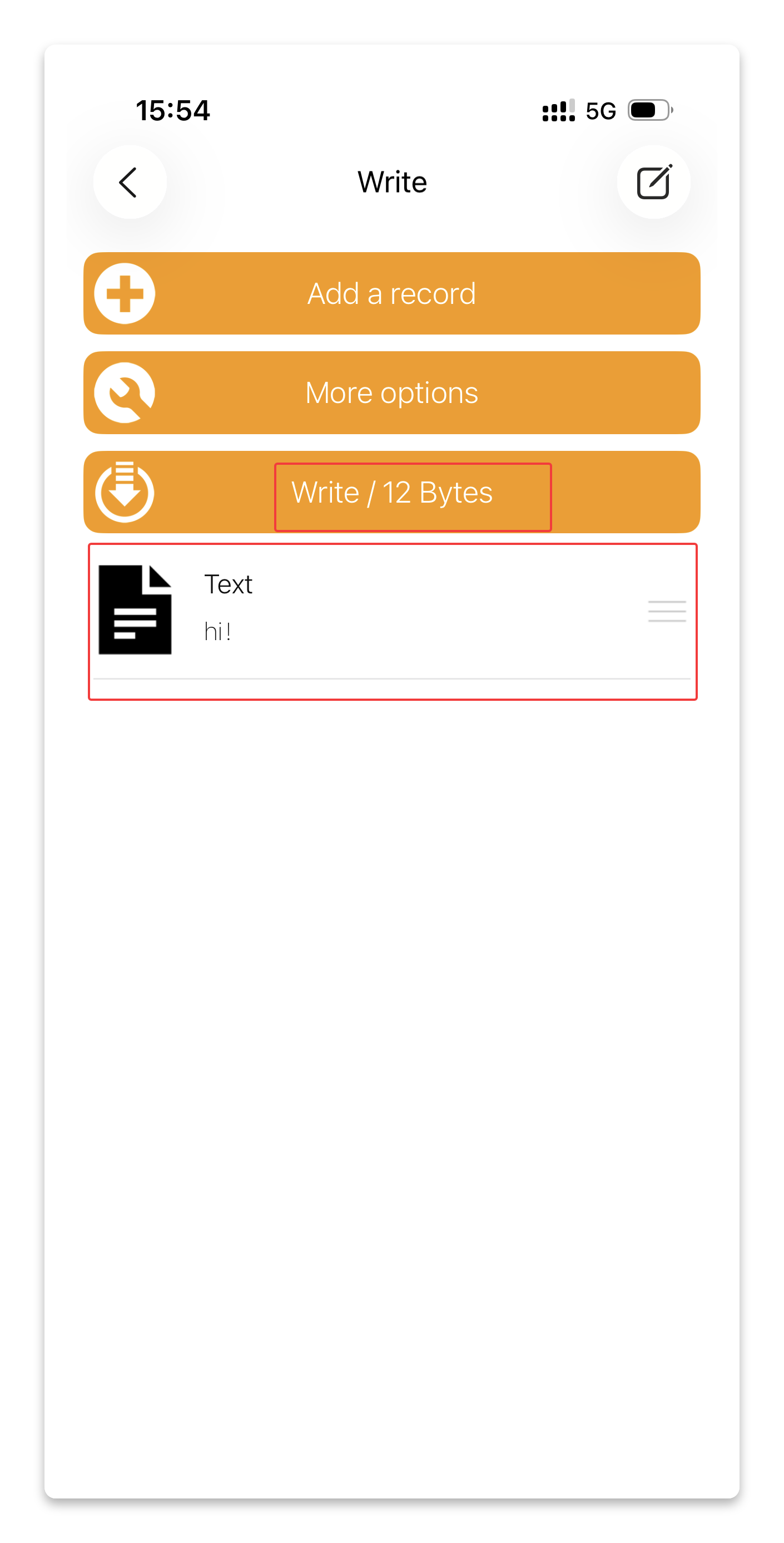
- Step 4. After the phone leaves the NFC field, the Serial Monitor prints
Storage: tag content saved to flash, confirming the content has been written to internal Flash.
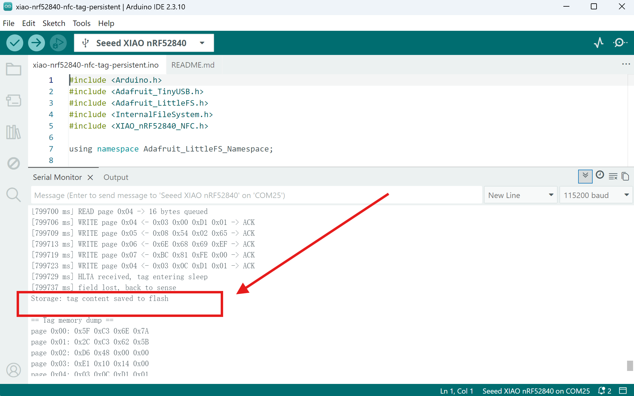
-
Step 5. Power-cycle the board — unplug the USB cable and plug it back in.
-
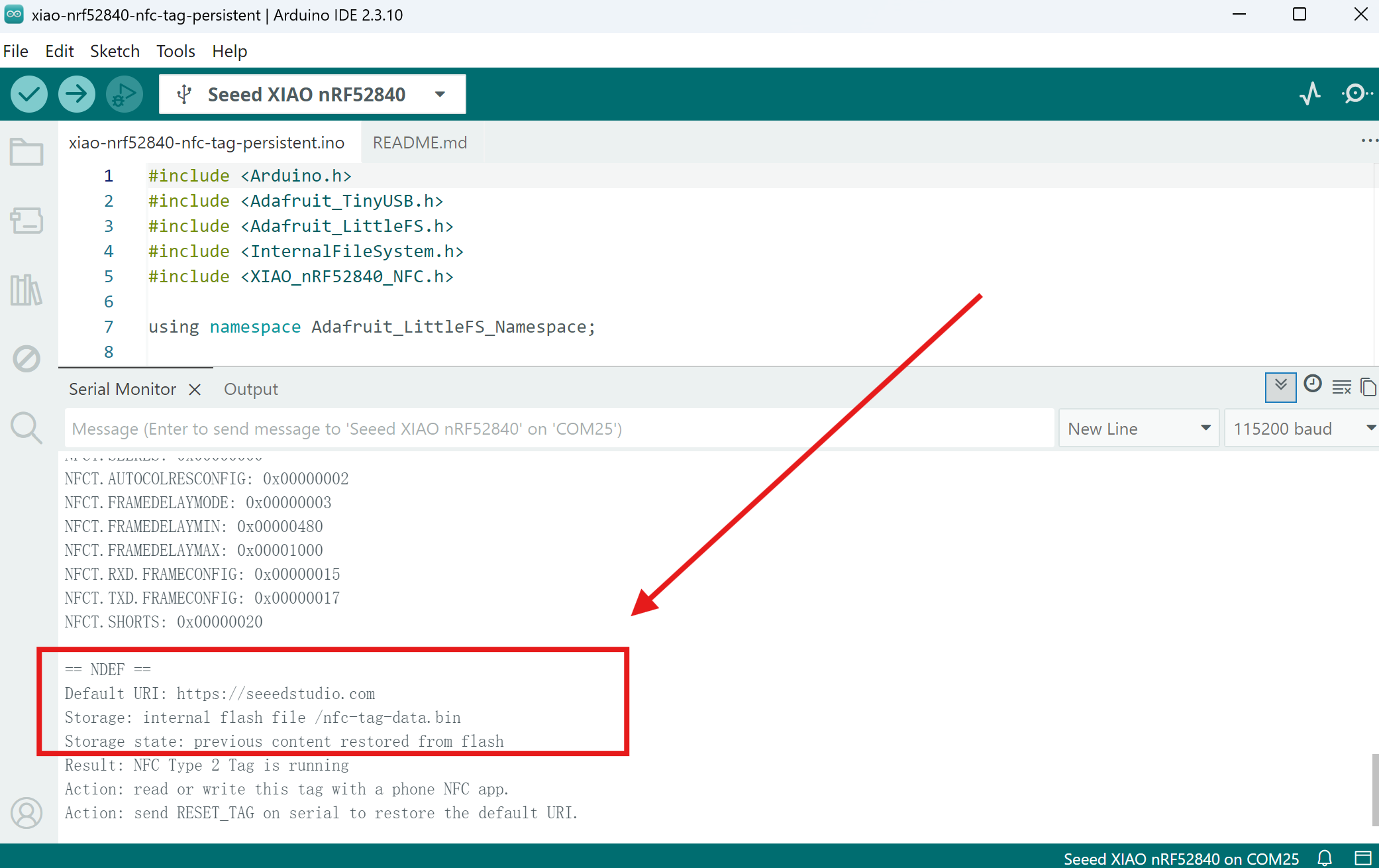
Step 6. After reboot, the Serial Monitor prints
Storage state: previous content restored from flash, confirming the written content has survived the power cycle.
- Step 7. Read the tag with your phone again. The phone should display the content written in Step 3 — even after the power cycle.
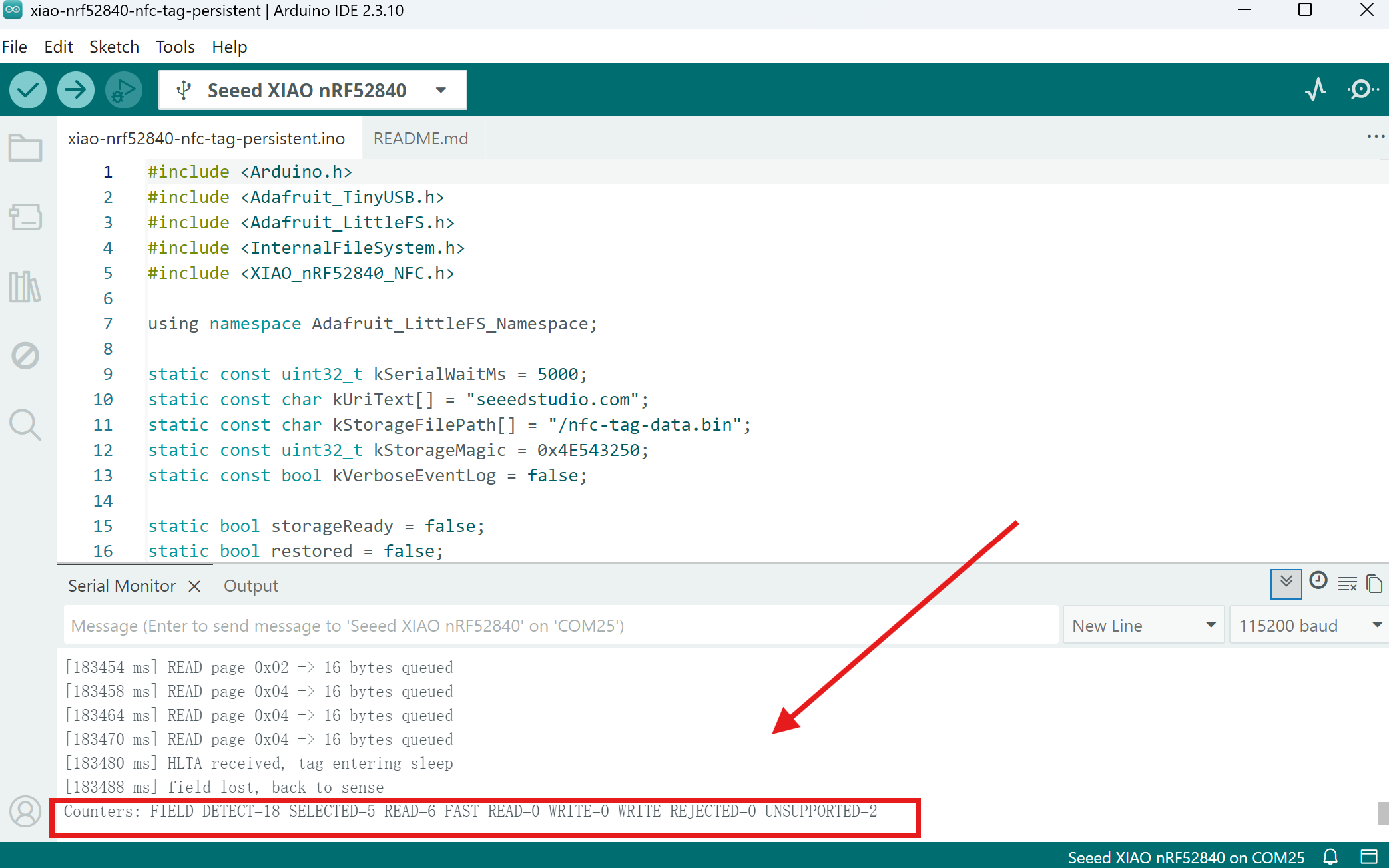
Key indicators:
The key indicators are the same as the Writable Tag — refer to the Writable Tag table for the full list.
Storage state: previous content restored from flashin the boot log is the core confirmation for Persistent: the data survived the power cycle.Storage: tag content saved to flashconfirms each write was saved to Flash.
In Step 7, the phone only reads the restored content — it does not write anything. So WRITE will remain 0 in the counters, which is expected. You only see WRITE > 0 during the earlier write session (Step 3–4).
- The stored content lives in the internal Flash filesystem (
/nfc-tag-data.bin), separate from the sketch area — it survives sketch re-uploads. - To restore the default URI at any time, send
RESET_TAGin the Serial Monitor. - Flash save happens once per write session after the phone leaves the field. If you remove the phone too early, the content may be incomplete — just write again to fix it.
Summary of the three demos:
| Demo | Data Storage | Survives Power Cycle | Writeable by Phone |
|---|---|---|---|
| Read-Only Tag | RAM | ❌ | ❌ |
| Writable Tag | RAM | ❌ | ✅ |
| Persistent Tag | Flash | ✅ | ✅ |
Resources
- [GitHub] XIAO_nRF52840_NFC Library — The open-source NFC library used in this tutorial
Special Thanks
Special thanks to andriandreo for the extensive real-world testing of NFC antennas (MOLEX 1462360051 and TAOGLAS FXR.07.A.DG) on the XIAO nRF52840, and to PJ_Glasso for the capacitor calculation guidance and iPhone compatibility troubleshooting.
If you encounter NFC issues not covered here, you may find helpful tips in the original forum thread:
Tech Support & Product Discussion
Thank you for choosing our products! We are here to provide you with different support to ensure that your experience with our products is as smooth as possible. We offer several communication channels to cater to different preferences and needs.